Newer Windows, starting with Windows 7 at least, requires the clocks to be in sync for the login/authentication to work. The confusing part is that if it fails, it doesn’t tell you why, leading you to think your password was wrong.
Turns out this time, I’m trying to inject files to a Windows 2000 machine (a logic analyzer). After some Googling, this website showed me it could be a time issue. The RTC on that motherboard was alright, and showing that it’s 2018, but after a close look, the timezone was EST (GMT-7) while I’m on PST (GMT-8), so the clock is off by one hour!
I was skimming over the manual that came with my 54831M, which is exactly 54831B except they included a technical manual TM 43-6625-915-12, which Agilent basically rearranged their user manual and service manual into one book. The scope is called OS-303/G.
With this arrangement, I noticed a few bits of interesting information was buried in the theory of operation (also shown in the civilian’s service manual):
The front panel keyboard uses UART (RS-232) to talk to the interface board
The power supply is 440W
Not very useful in terms of repair, but useful if you are into modding stuff.
I was repairing a HP 3560A that does not start up at all. The system is very modular that there are only 3 main units: LCD/keyboard/DSP board (A1), Main Processor board (A2) which manages power sources and contains the backlight inverter as well, and the analog section (A3).
Obviously the first thing to look for is where the power is managed, which is the main processor board (A2). I bought another unit (with a different defect, i.e. it boots) hoping to use it as a reference but to my surprise, the A2 board is slightly different! In fact, the LT1120 voltage regulator that I’m seeing unusual pulses in V_out pin (should be flat) is not even there!
I’ll save the repair story for another post, but for information preservation purposes, I took pictures of the two different revisions of the A2 assembly from 3 units, shown below:
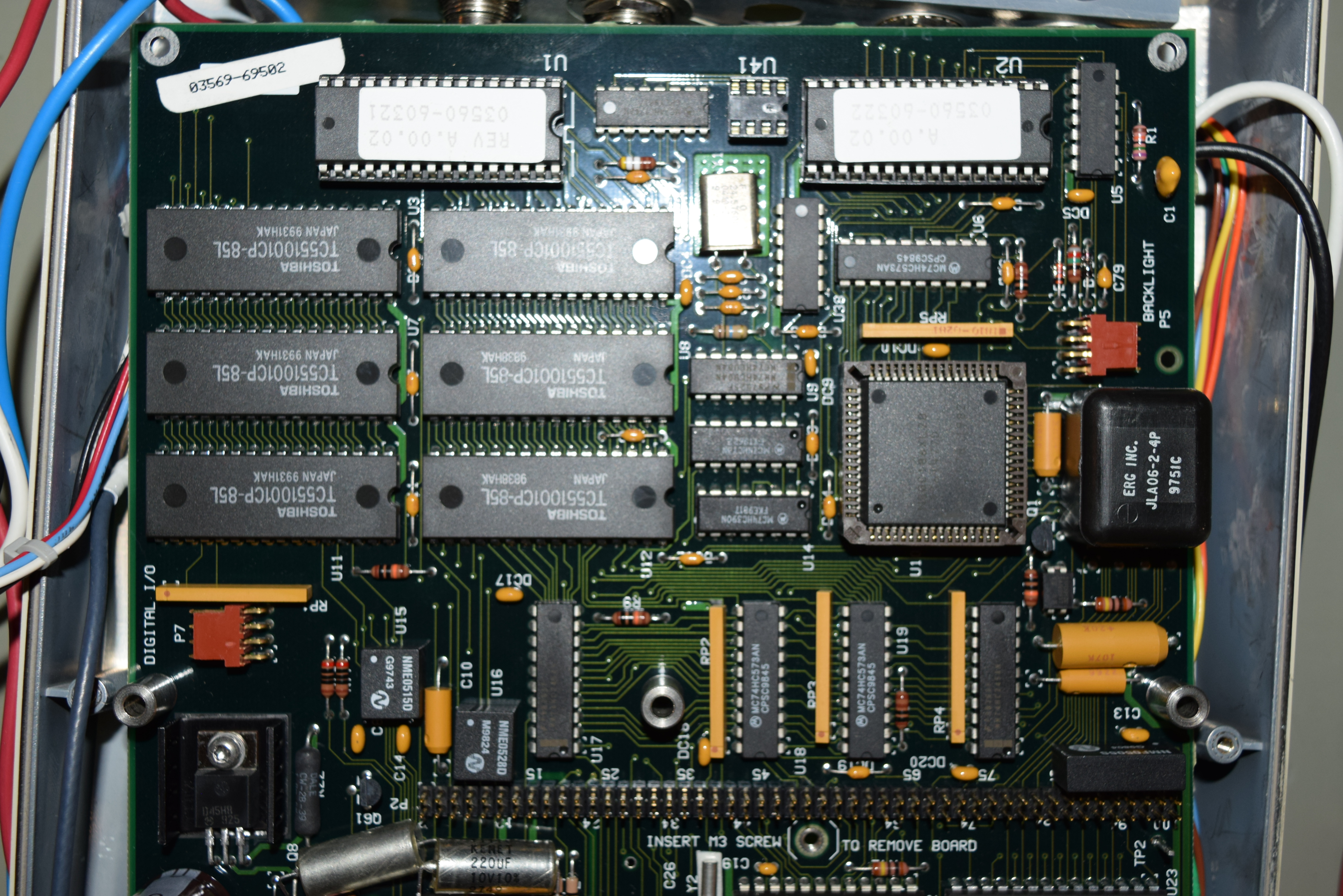
New: 03569-66502 Rev B
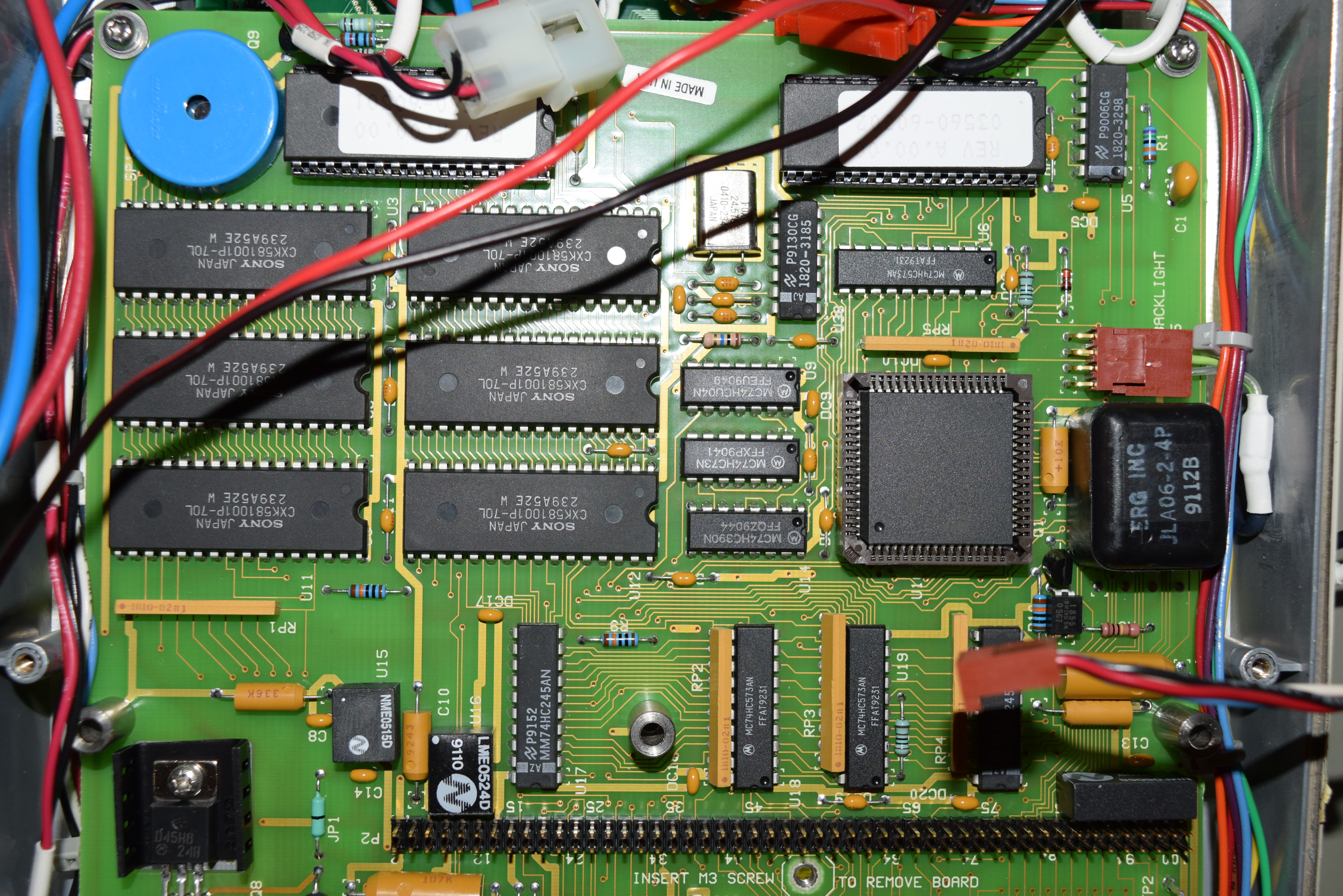
Old: 03560-66502 Rev B, Rev C
The top part of the board is essentially the same. The new board uses Toshiba TC551001CP-85L while the old board uses Sony CXK581001P-70L for Static RAM. They are likely pin compatible and it’s just availability differences. (Ignore the randomly placed caps at the bottom of the new A2 board. I desoldered them to test if they are good).
03560-66502 (Top)
03569-66502 (Top)
If you pay close attention, at the top of the new revision board, it has an unpopulated DIP-8 socket and an extra 74HC174N chip, and an extra digital I/O port at the mid-bottom left edge below the SRAM. They are reserved for 3569A (a better version with a noise tracking generator) as it uses the same board. The old revision A2 board works for 3560A only. It’s a topic for another post.
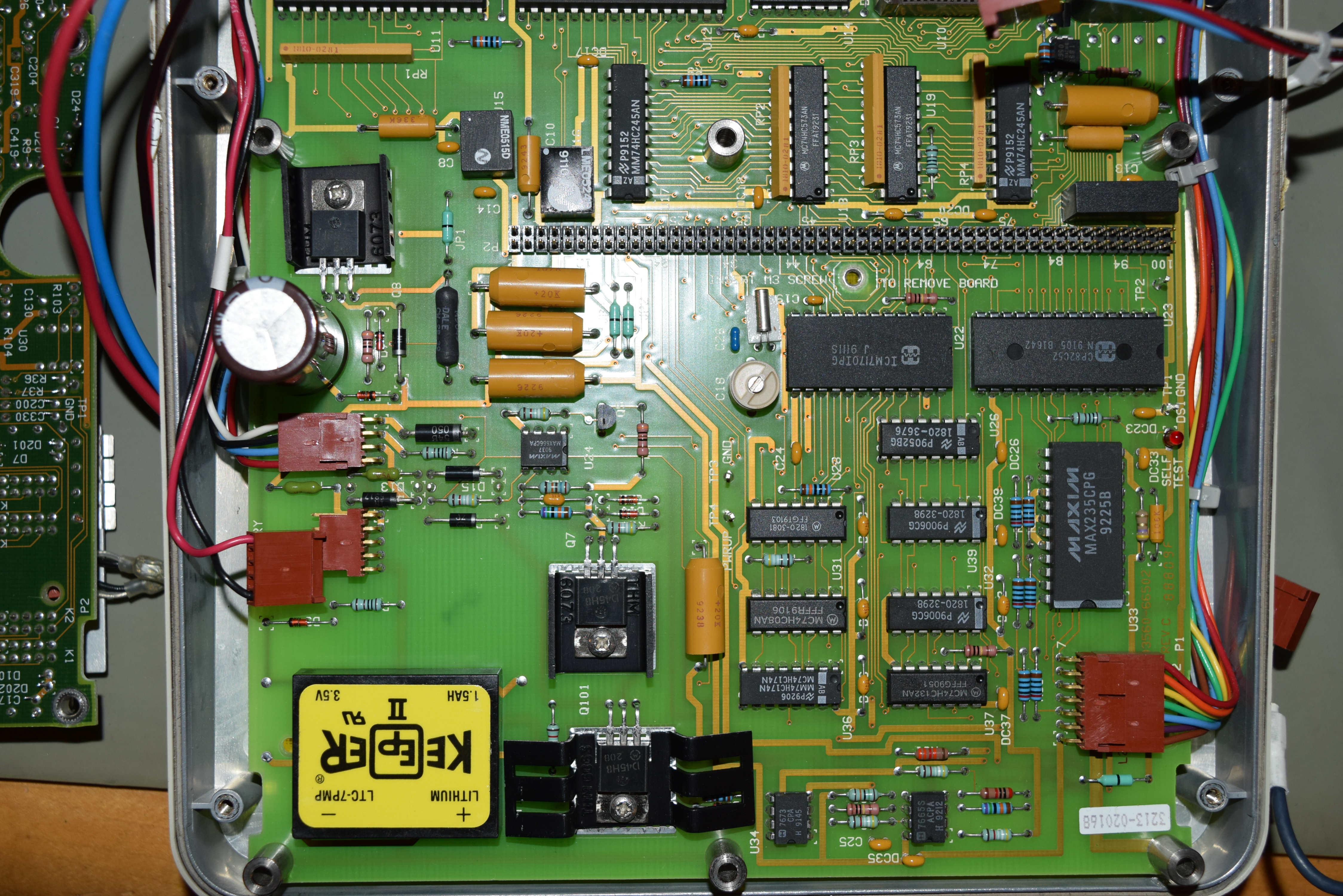
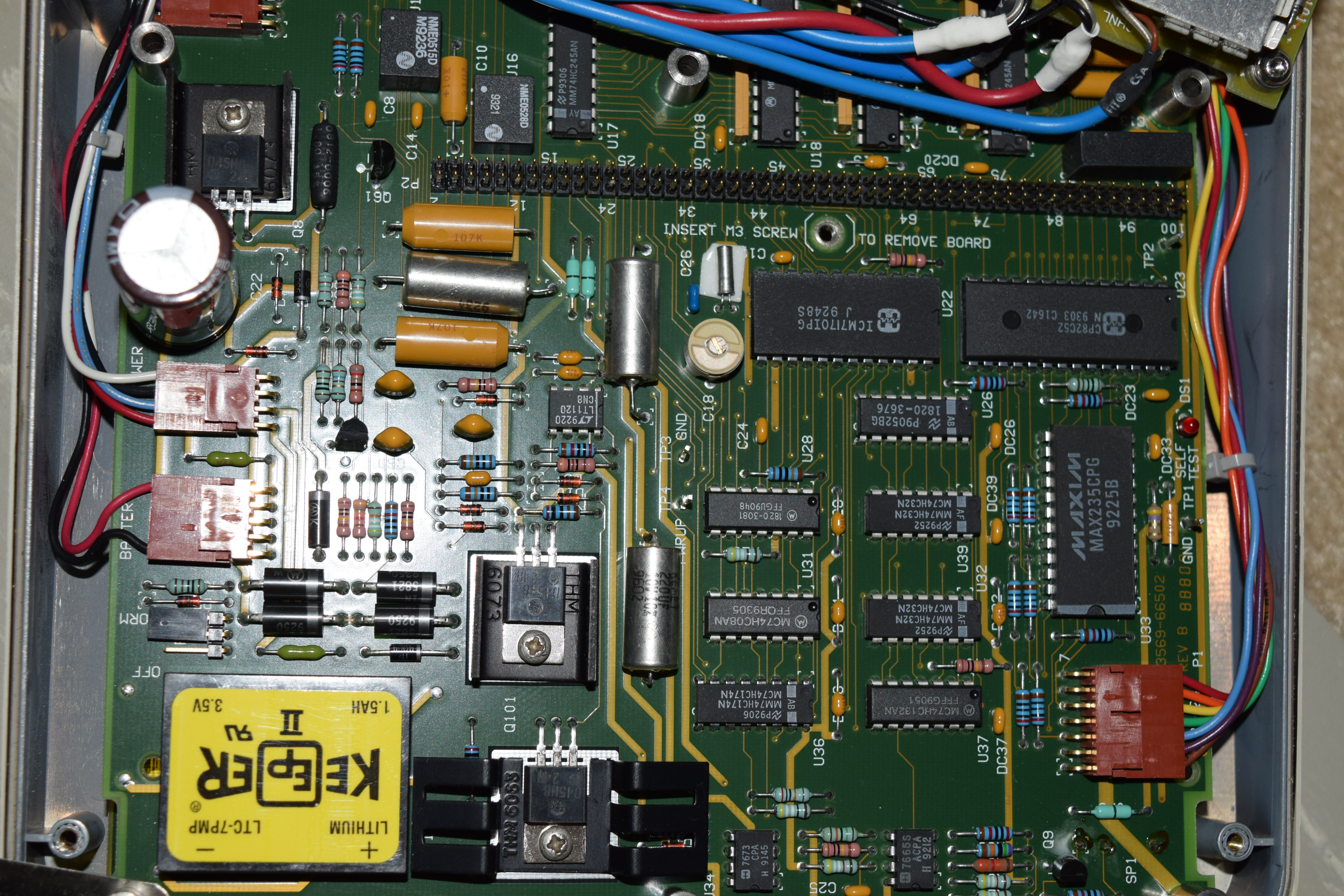
The bottom part is quite different. The classical 4-diode full-bridge rectifier on the new board is not shown at the main side of the circuit board for the old A2 assembly. The new board looked much denser.
03560-66502 (Bottom)
03569-66502 (Bottom)
Most importantly, the old board uses MAX666 as the 5V voltage regulator while the new board uses LT1120. The pinouts are different and chip features varies a little bit, so the power management section is not topologically identical.
There are no components on the back side of the new revision A2 board (they are both supposed to be single sided PCBs), but two diodes are squeezed in at the back of the old revision A2 board, and there’s an extra resistor flyover:
My suspicion is that the diodes are intentional as there are specific through-holes for them (most like they other half of the bridge rectifier), but the resistor is an after-spin rework.
Finally, for information preservation, I also took pictures of the old A2 board (03560-66502 Rev B) from another unit I have:
03560-66502 Rev B (Bottom)
03560-66502 Rev B (Top)
If you consider the relative ease of use for less computer savvy people, 3560A/3569A is versatile yet designed specifically for the most commonly used measurements in acoustic and mechanical vibrations. It’s still excellent value for what it offers despite it’s a made decades ago since it doesn’t overwhelm you with convoluted choices so you can gets the job done once you’ve setup your recipe.
HP has designed the unit very well, with the exception of the LCD screen which cannot be found on earth, all through-hole components on single layer board and well organized structure and silkscreen makes servicing a pleasure.
I can repair and rebuild 3560A / 3569A with new battery pack and clock battery. The hardest problem to track down is no-boot, and the hardest surgery to make is the backlight. I also know how to talk to the unit from modern computers as well, so data capture is not a problem. Call me at 949-682-8145 for consultation.
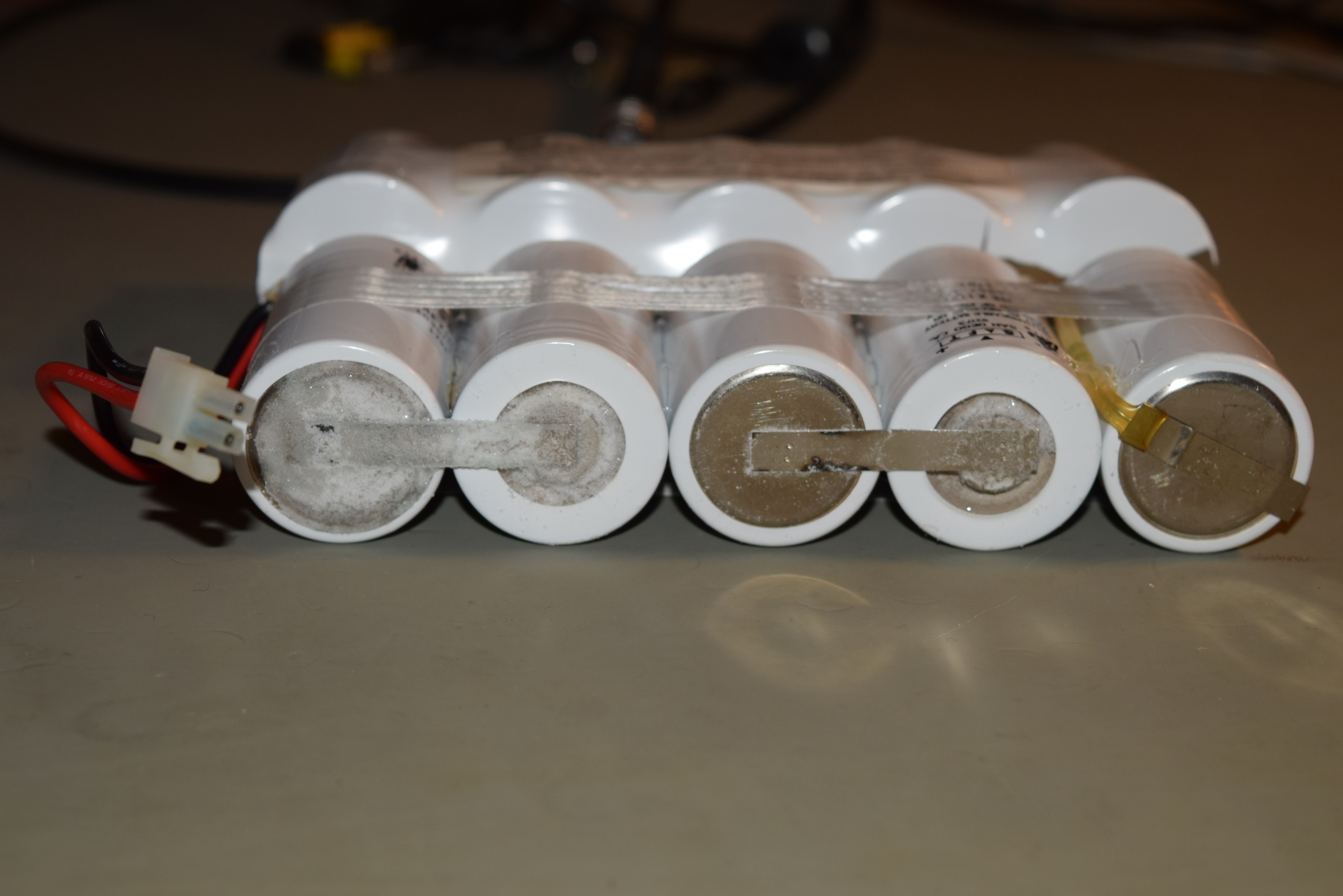
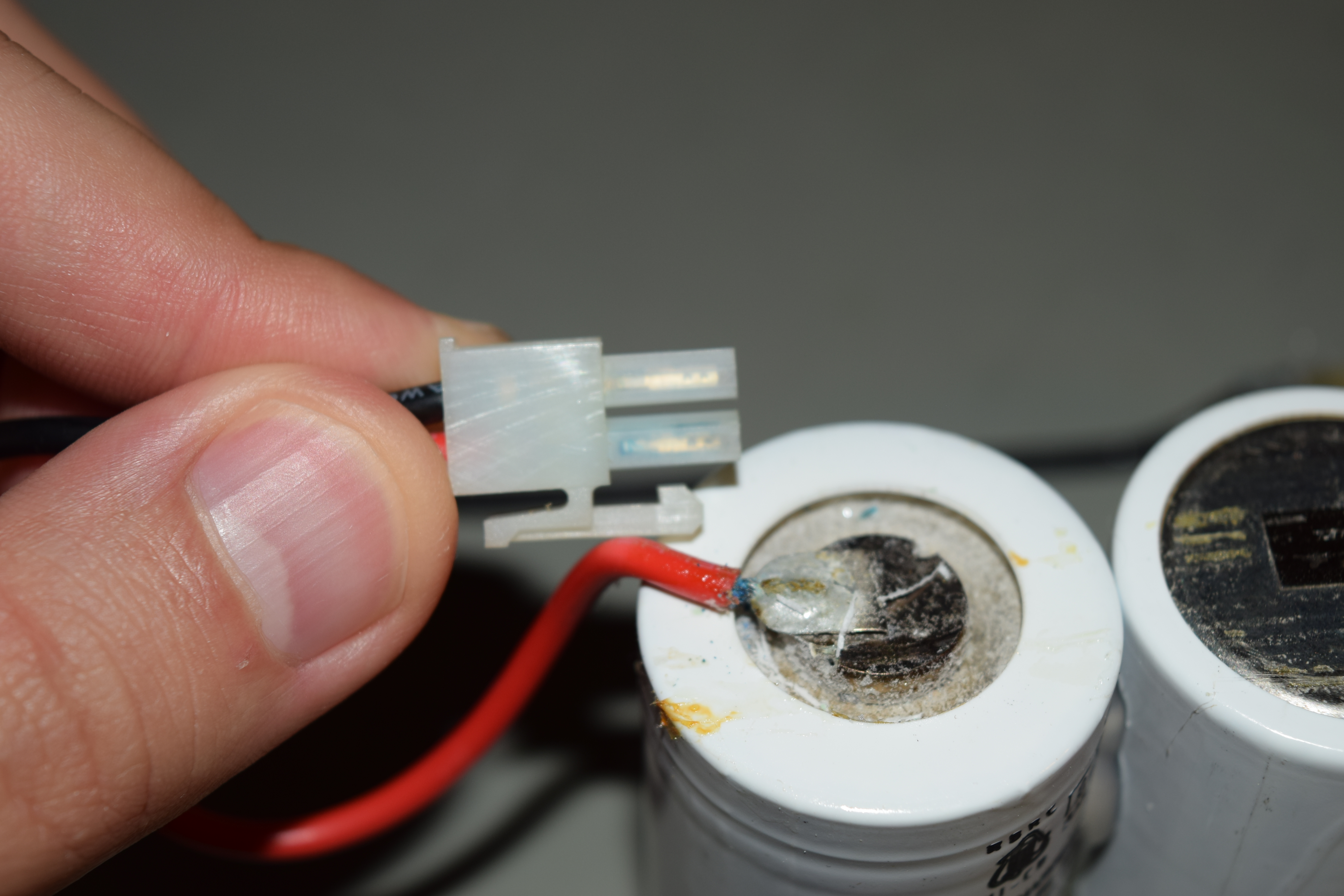
If you have an original HP 3560A sitting for years and haven’t changed the battery pack yet, it’s guaranted to be dead. Here’s the shell of the battery pack 1420-0584:
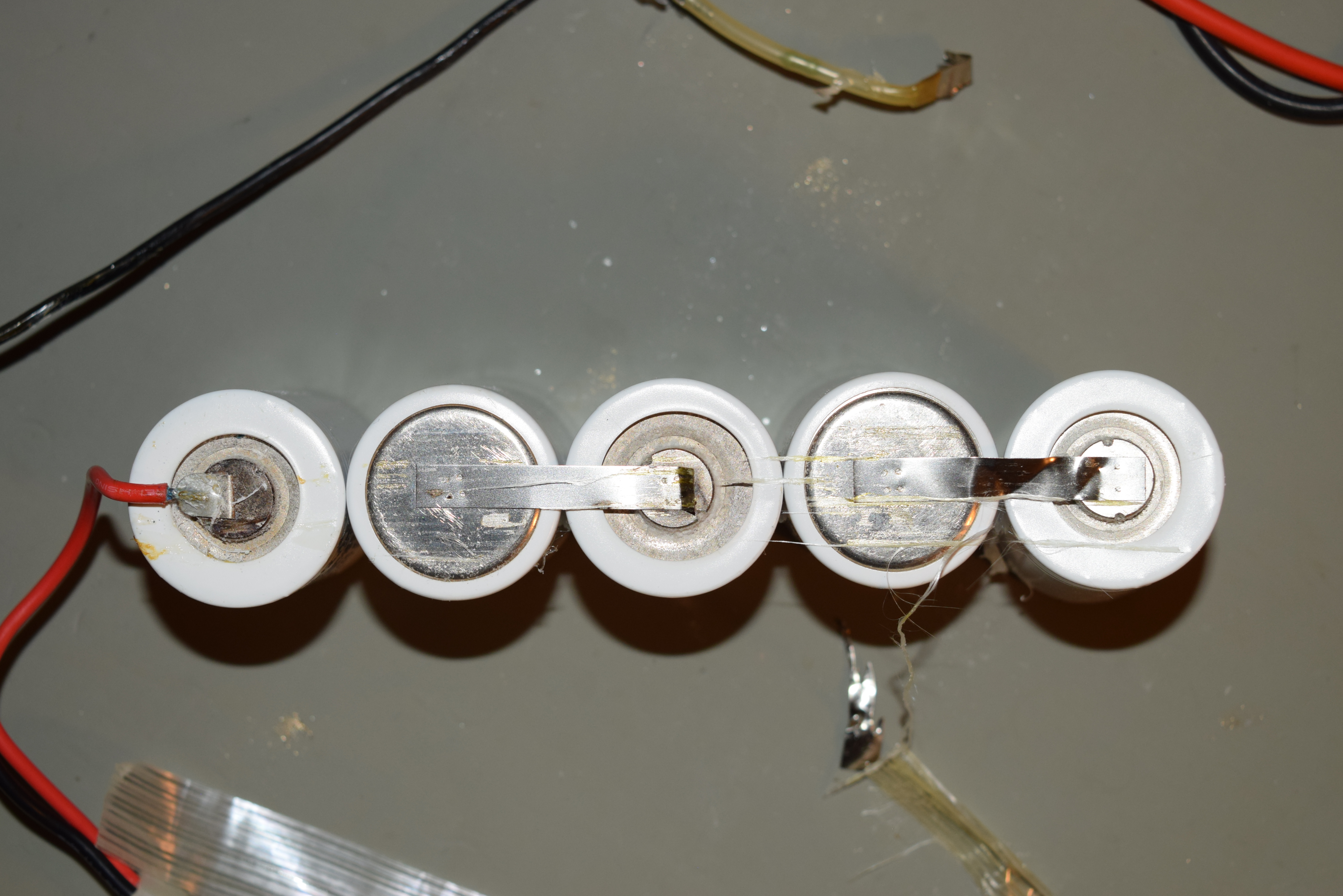
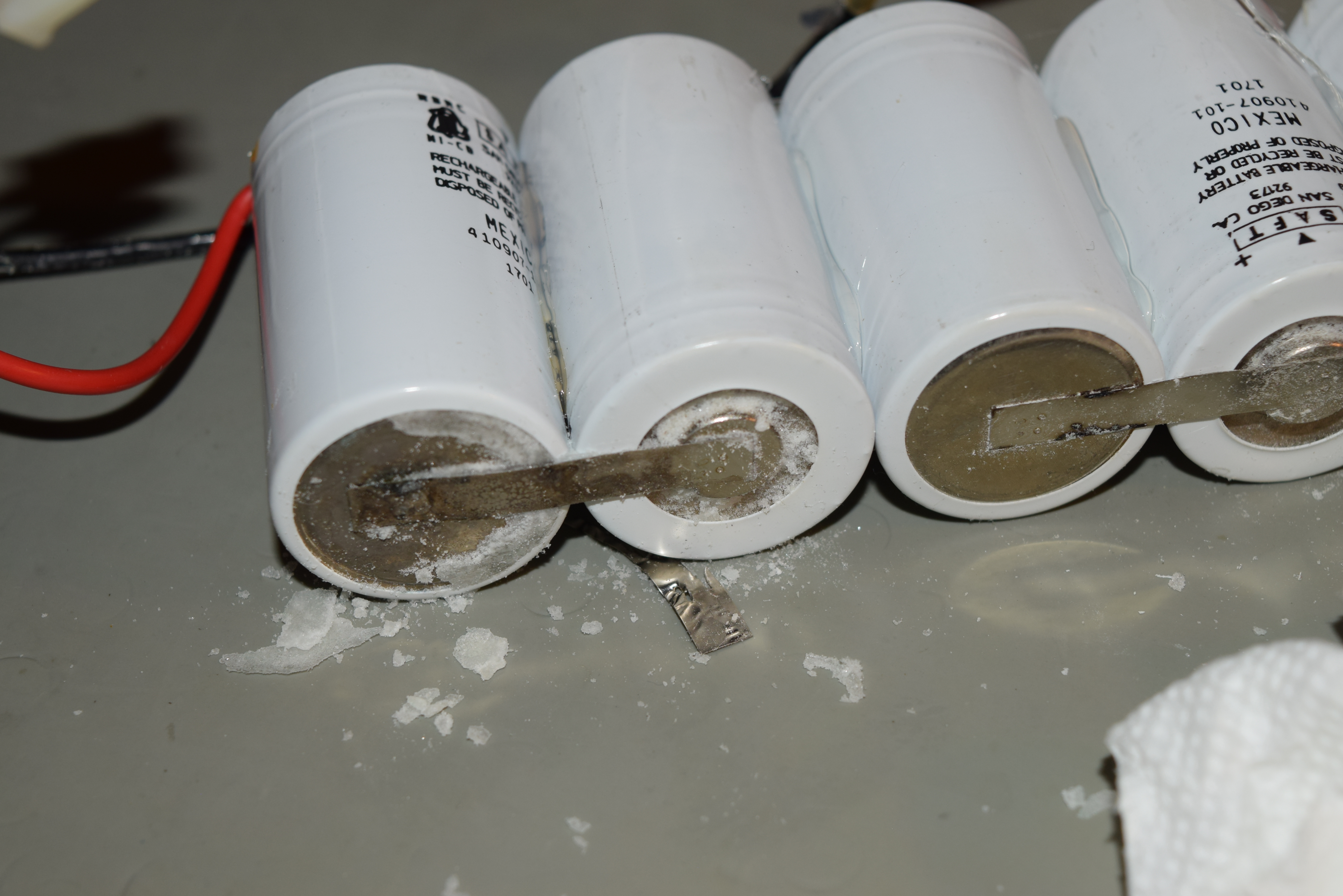
Just to give you no hope attempting to reused the battery pack, I dissected one of them and show you how much of a disaster inside it:
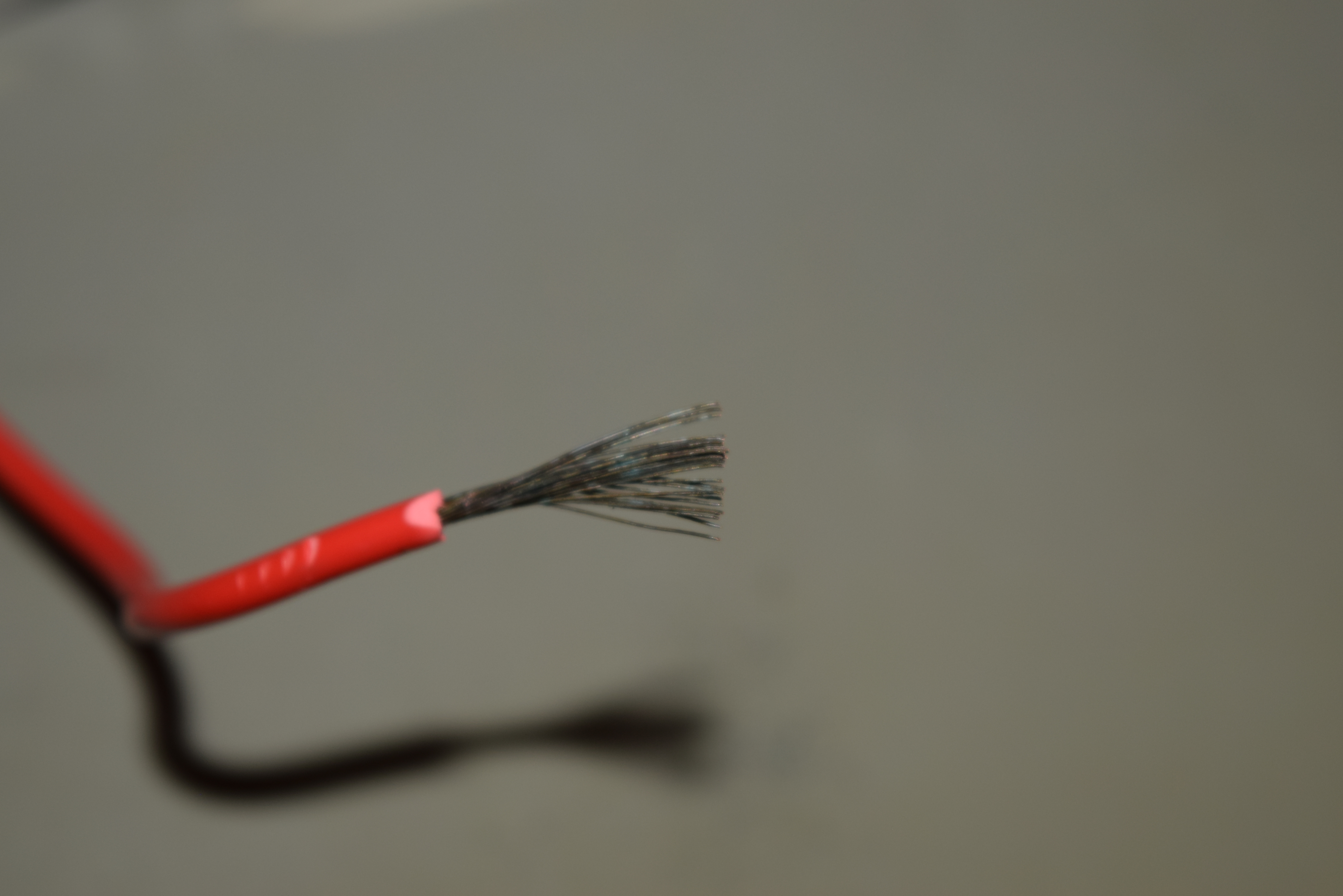
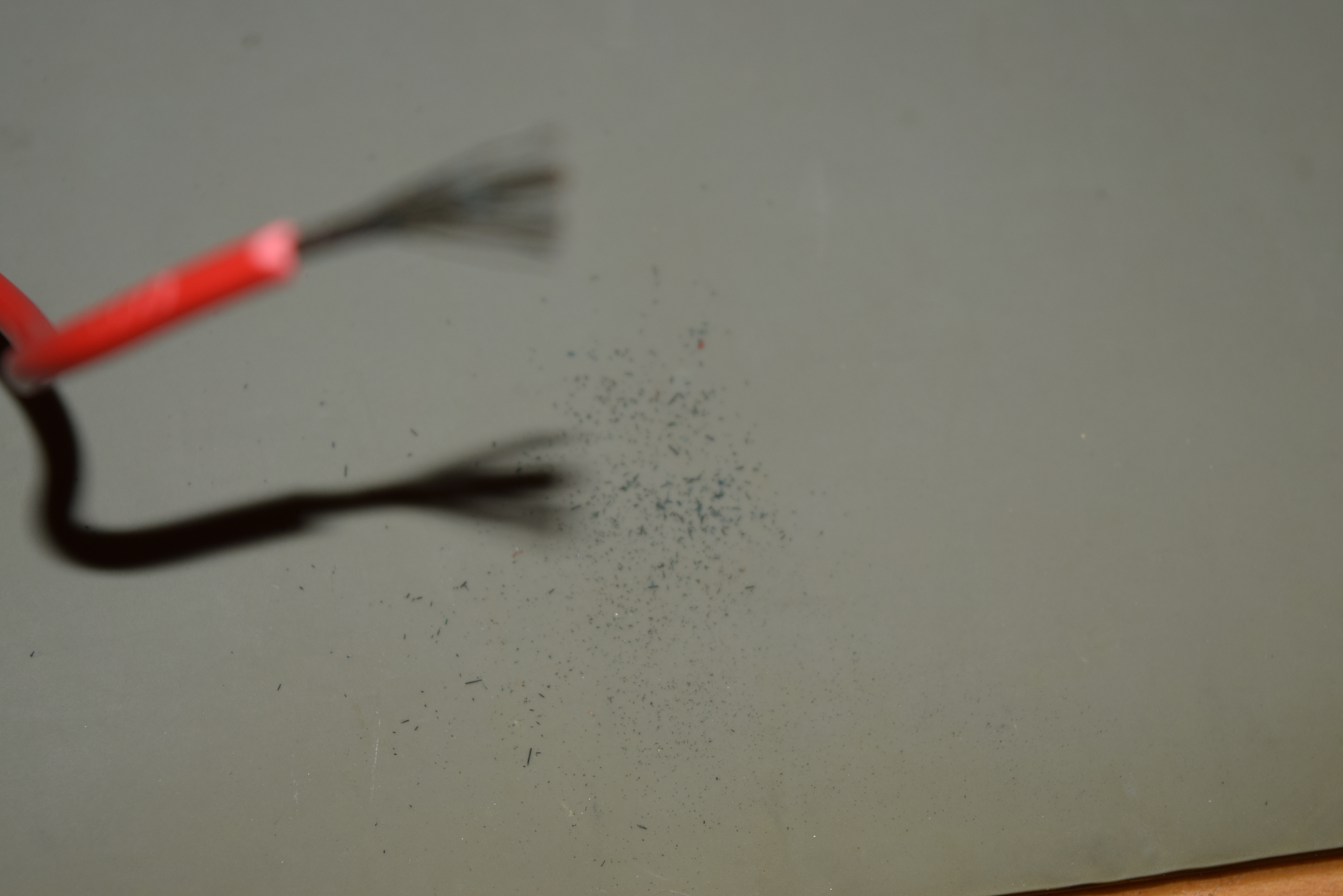
This pack has been sitting for so long that the cathode (+) wire is severely corroded (not all of them are like this). Even the connector turned green. I cut open the wires and gave it a tap, and a bunch of copper oxide bits falls off.
Now that I acquired the tools, parts and practice to make one from scratch (I used to need the old battery pack). It’s not cheap (given the tools, research effort, and most importantly, small quantity), but I can custom build them for you if you don’t want to deal with the hassle and steep learning curve.
The first pack is the most expensive, additional ones are much cheaper because of the reduced overhead. Lead time is around 1~2 weeks unless you pay extra for me to express order the ingredients.
You can call me at 949-682-8145 or just go to humgar.com.