HP 54502A Datasheet typo about AC coupling

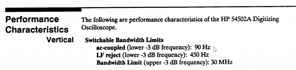
The cutoff frequency of 10Hz on the datasheet is a typo. Better scopes at the time claims 90Hz. 10Hz is just too good to be true.

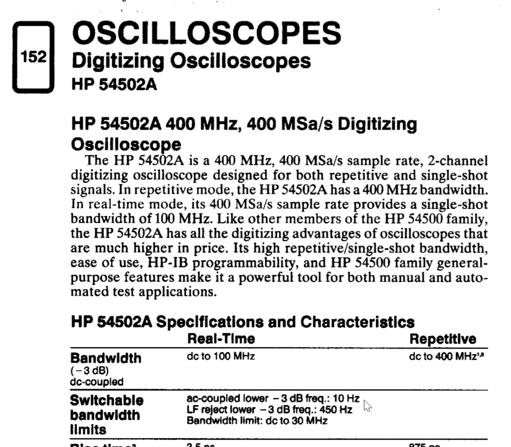
Found the specs from the service manual:

Don’t be fooled by the -3dB cutoff and ignore how wide the transition band can be (depends on the filter type and the order). Turns out this model has a very primitive filter that AC couple mode still messes square waves below 3kHz up despite the specs says the -3dB is at 90Hz. You better have a 30+ fold guard band for old scopes!

Remember square wave pulse train in time domain is basically a sinc pulse centered at every impulse of the impulse train in frequency domain superimposed. Unless you have a tiny duty cycle (which is not the case for uniform square waves, they are 50%), the left hand side of the sinc function at 1kHz fundamental still have sub-1kHz components that can be truncated by the AC coupling (high pass filter).

Loading

Keysight Calibration (Performance Validation) for Probes Specifically 1152A

I recently sent a 1152A probe for calibration and was surprised to find out the data on the calibration report tells little about how the tests are done and under what settings. I searched the throughly and called tech support and they confirmed my observation the performance validation procedures are not mentioned anywhere in the published documents.

I called Keysight cal department and was able to reach a super-helpful tech, Markis, who did the calibration for my 1152A probe and he explained to me how the calibration process is done when I called.

HP/Agilent/Keysight probes using AutoProbe interfaces are powered by 1143A (that was intended for 54701A probes) through a N1022A adapter (the one used in 81600 Infiniium DCA) for Keysight’s calibration process, which measures uncompensated probe-only performance. I saw the calibration reports from 3rd party-labs, and probes are are calibrated inside the oscilloscope they are used in, and therefore it’s measuring a compensated system (scope+probe) performance.

There is a 30 minute warm up period.

The procedures resembles to what’s detailed in the old 1144A probe user/service manual, (page 10-14) with the exception that the ‘Gain Accuracy’ done there is ‘AC gain accuracy’ (at 1kHz, 1Vrms) instead of ‘DC Gain Accuracy’ claimed on the report. In fact, given that it’s simply measuring relative error (multimeter reading of the probe BNC output divided by the 5V Fluke Calibrator reference) at one voltage setting, I believe it should be called ‘DC measurement accuracy’. The number on the calibration report was divided by 10 times since 1152A is a 10:1 probe.

The bandwidth test for 1152A is simply looking at attenuation at the advertised bandwidth (2.5Ghz for 1152A) relative to 50Mhz (low frequency reference set at 0dBm).


Loading