Improved code for Toner Reset SP C250SF/DN

This is based on the Raspberry Pi implementation of the Toner chip reset:

https://gist.github.com/joeljacobs/c57550cdb4e68e3b86d6b89fb58f305d

I am using a Raspberry Pi Zero W so the chip is BCM2835 instead and I can use 100Kbps/400KBps instead of 9600 baud as in the original code

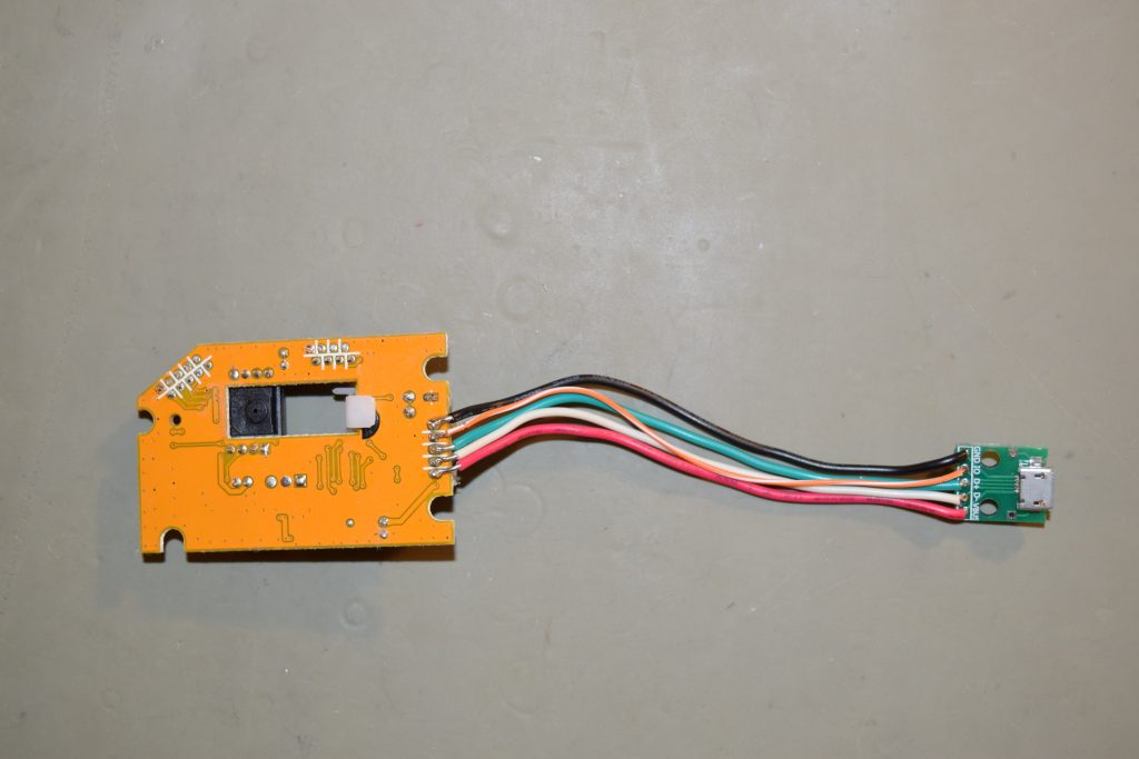
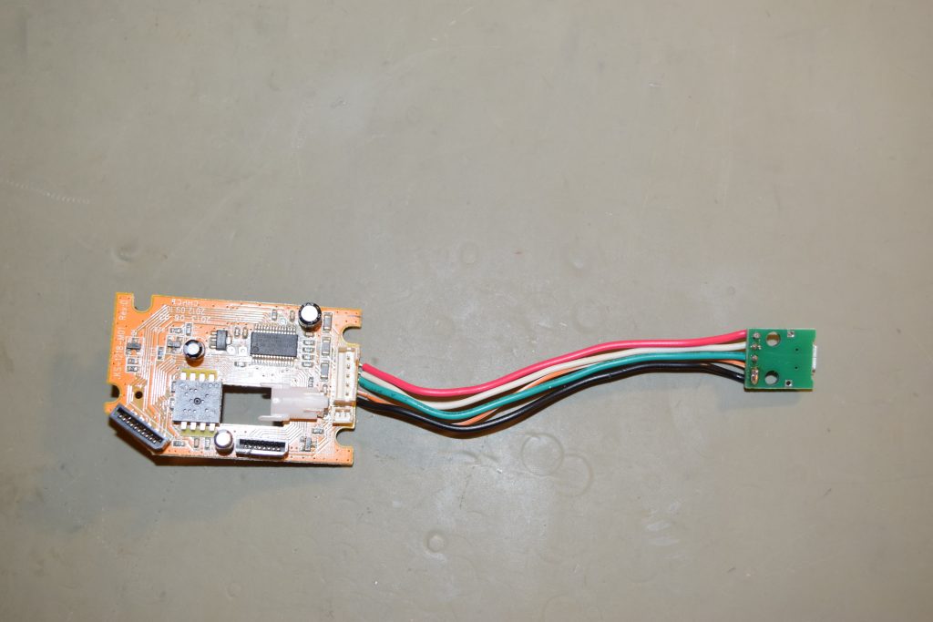
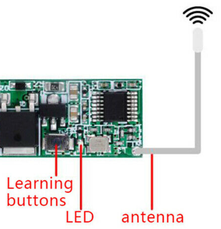
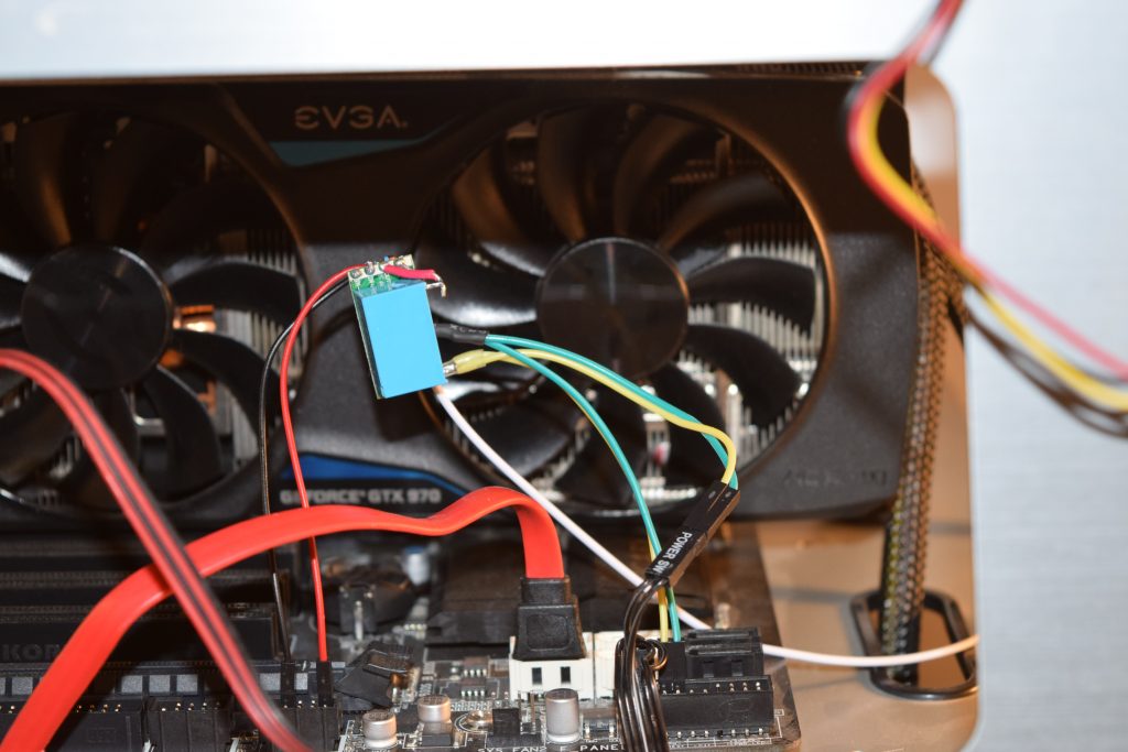
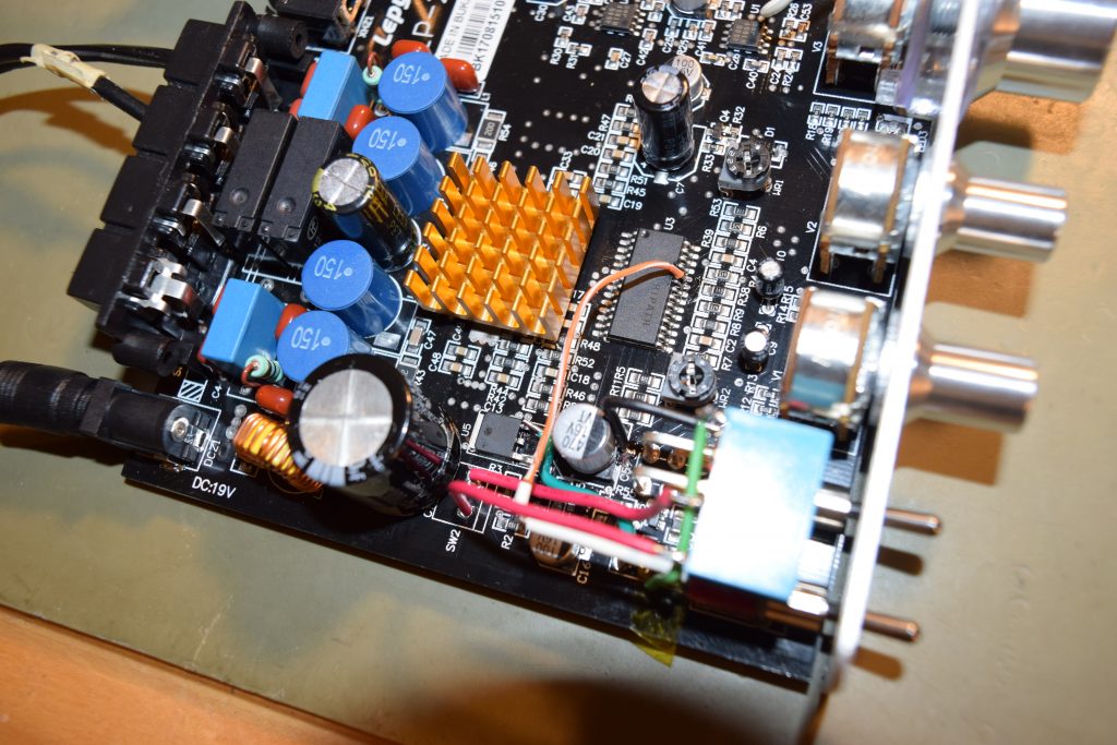
The electrical pins we need is clustered on to top left, Pins 1 (3.3V), 3 (I2C SDATA), 5 (I2C SCLK), 9 (Ground)

Raspberry Pi Zero GPIO Pinout, Specifications and Programming language

While looking for the pinouts (https://pinout.xyz/pinout/i2c), I discovered a useful tool called i2cdetect that allows me to find out the address of the chips which means I can write a program automatically figure out the right image to load to the chip without looking:

sudo apt-get install i2c-tools
sudo i2cdetect -y 1
Sorry I forgot where I got this image from.
Please remind me in the comments section if you find out who should I credit it to.

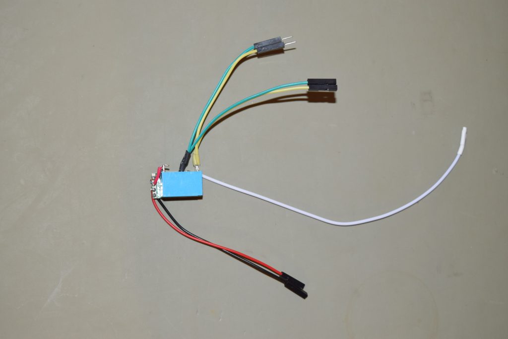
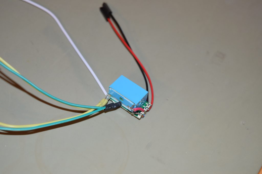
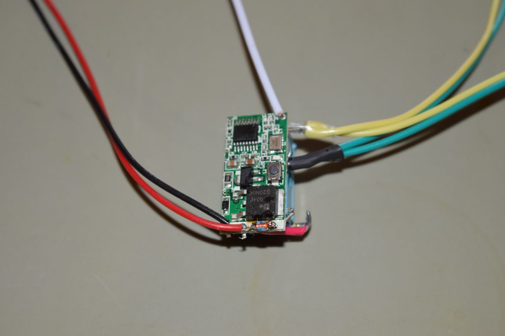
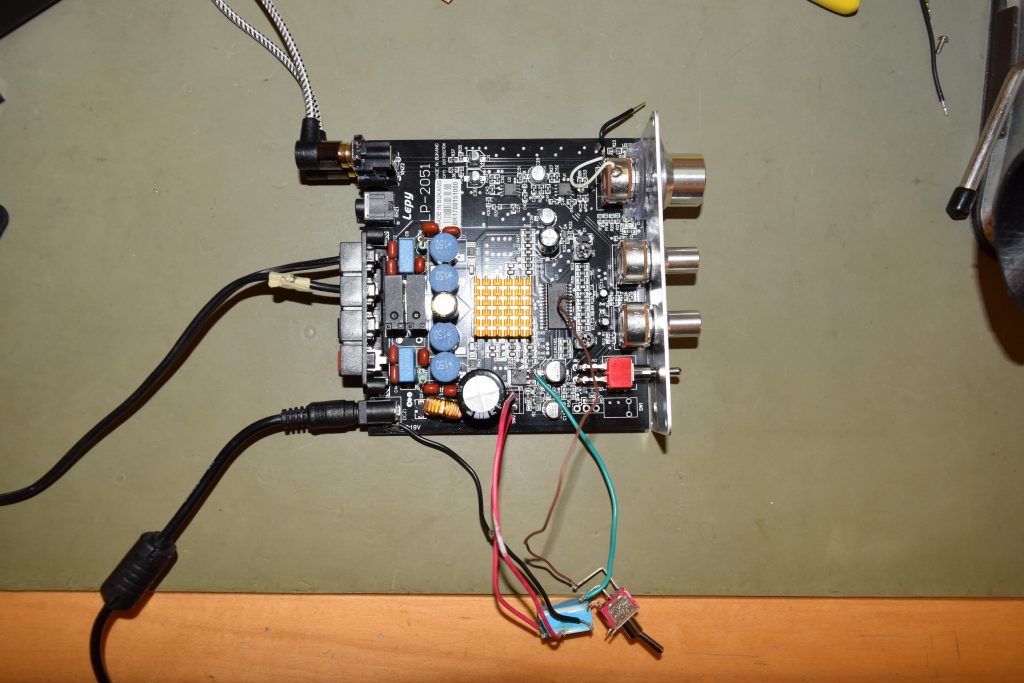
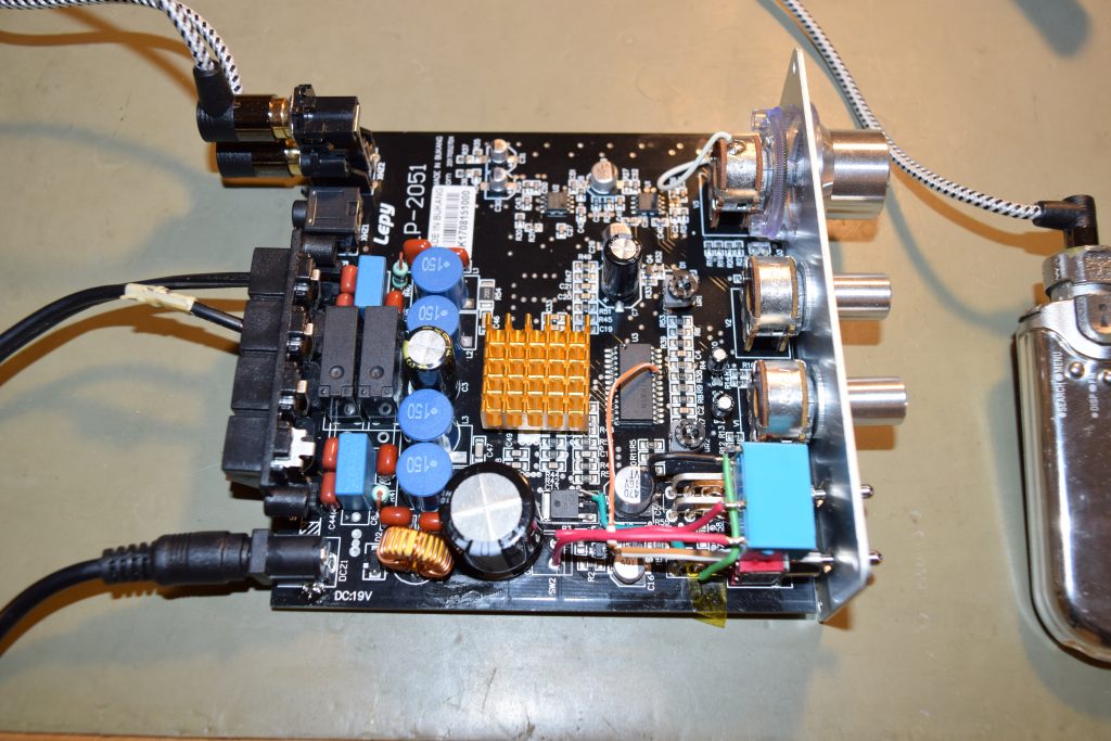
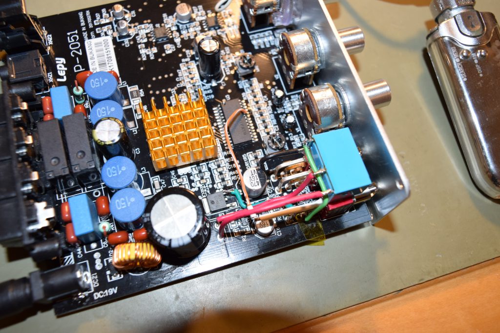
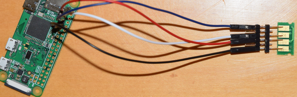
Since I don’t have cheap pogo pins lying around, I took the 2.4mm pitch (the standard size used in PC, Arduino and Raspberry Pi) jumper block I have (so all pins are set at equal lengths to make simultaneous contact) and hope somehow there’s 4 pins that kind of align with the contact, and it did. See pictures here:

Can press the pins down by using jumpers

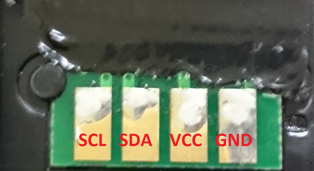
You might be worried about shorting into the next pin or hooking something up in reverse damaging the chips, but luckily the chips survived. My guess is that it’s a good design to put the Vcc next to Ground on one side instead of making it symmetric so the polarity can be reversed. When reversed, SCL is set to low (Ground), SDA is pulled up to Vcc while there is no power supply, so no damage is done. Brilliant! The worst case for my poorly aligned jumper block is that SDA and Vcc might touch each other, but it doesn’t matter because it’s a perfectly legal hookup (just not communicating)!

So no worries if you didn’t touch the pins right! The only case it might go wrong is if you intentionally flip the block and slide it by two pins (reversing Vcc and Ground). Other cases (you are likely going to run into) are pretty much data lines getting hooked high or low levels while power lines not getting any supplies.

I’ve designed the program that it’ll detect the chip if you hook it up right and immediately program the chip (takes only a second), so you don’t have to hold the jumper for too long to worry about unstable contacts.

#!/bin/bash

# This program detects rewrite the toner chips to "full" for a Ricoh SP C250SF/DN Printer using Raspberry PI (defaults to BCM2835 models such as Raspberry PI Zero)

# The chip data is in file named "black" "cyan" "magenta" and "yellow".
# The pad closest to the edge is GND (-> Pin 9), followed by VCC (-> Pin 1) , DATA (-> Pin 3), and Clock (-> Pin 5).

# Be sure i2c is enabled and installed (it's turned off by default) on Raspbian

# This line is disabled because it takes too long to unregister i2c_bcm2835 to start from a clean slate
# modprobe -r i2c_bcm2835

# This program needs sudo permissions as it involves direct access to hardware
if [[ $EUID -ne 0 ]]; then
  echo "Need root permissions as this code involves direct hardware access. Try sudo"
  exit 2
fi

# Sets the baud rate
modprobe i2c_bcm2835 baudrate=400000

# Install i2cdetect if not exist (This idiom uses short-circuit OR for conditional exec)
command -v i2cdetect > /dev/null 2>&1 || {sudo apt-get install i2c-tools}

# Create I2C address to color map
COLORS=( [50]="yellow" [51]="magenta" [52]="cyan" [53]="black" )
# Detect chip I2C address
I2C_address=$( sudo i2cdetect -y 1 | grep 50 | sed -e 's/50: //;s/-- //g' )
# Keep the 0x5* address lines since only 0x50~0x53 is valid. Strip the 50: header, discard all "--" entries, and you are left with the detected address
HEX_I2C_address="0x$I2C_address"

# LED flash function(s)
target_device="/sys/class/leds/led0/brightness"
# This accounts for breaking changes (by renaming led0 to ACT) from Bookworm
[ -f ${target_device} ] || target_device="/sys/class/leds/ACT/brightness"

function turn_off {
  echo 0 > ${target_device}
}
function turn_on {
  echo 1 > ${target_device}
}
function toggle {
  # PI Zero only has 1 power LED which is on/off 
  # Reads 0 for OFF and 255 for ON
  readin=$(cat ${target_device})
  # Condition 255 to 1 to reduce platform dependency
  state=$[$readin>0]
  # Not equal to 1 is XOR (flip)
  flip=$[$state != 1]
  # Display output
  echo $flip > ${target_device}
}

function flash_once {
  period=${1:-0.5}

  toggle
  sleep $period

  toggle
  sleep $period
}

function flash {
  times=${1:-1}
  period=$2
  for((i=1; i<=times; i++)); do
    flash_once $period
  done
}

if [ -v COLORS[I2C_address] ]; then
  # Meat
  color=${COLORS[I2C_address]}
  echo "Detected toner chip for color: $color"

  echo "Short flashes before starting. Long flashes after done. Ctrl+C if you want to terminate get back to prompt earlier during long flashes."
  flash 5 0.1

   # "address" counter sync up with the hex code index in file
   printf "Writing"
   address=0;
   datafile="${BASH_SOURCE%/*}/${color}"
   for i in $(cat $datafile); do
     i2cset -y 1 ${HEX_I2C_address} $address $i;
     address=$(($address +1));
     printf .
     flash 1 0
   done
   echo "Done!"
  flash 10 0.5
else
  echo "Invalid I2C address for SP C250DN/SF toner chips. ${I2C_address}"
  exit 4
fi

Turns out Linux’s dot sourcing (bash calling) syntax is relative to your current folder, not the scripts’ folder. So if you have one script calling another in the same folder when you are not currently at the same folder as the script (e.g. startup automation), the relative paths will be wrong. So instead of ./ , you should use this prefix instead:

${BASH_SOURCE%/*}/

I chose to flash the board’s only LED light quickly before starting and blink slowly a few times after it’s done for visual clues. It’s entirely optional. Here’s the guts of the code without the fancy indicators:

#!/bin/bash

# Sets the baud rate
modprobe i2c_bcm2835 baudrate=400000

# Create I2C address to color map
COLORS=( [50]="yellow" [51]="magenta" [52]="cyan" [53]="black" )

# Detect chip I2C address
I2C_address=$( sudo i2cdetect -y 1 | grep 50 | sed -e 's/50: //;s/-- //g' )
HEX_I2C_address="0x$I2C_address"

if [ -v COLORS[I2C_address] ]; then
  # Meat
  color=${COLORS[I2C_address]}

  # "address" counter sync up with the hex code index in file
  address=0;
  for i in $(cat ${color}); do
    i2cset -y 1 ${HEX_I2C_address} $address $i;
    address=$(($address +1));
  done
else
  echo "Invalid I2C address for SP C250DN/SF toner chips: ${I2C_address}"
fi

Download the package. Run program_toner

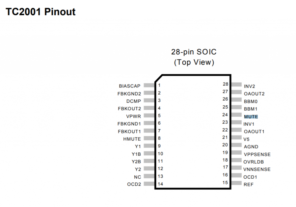
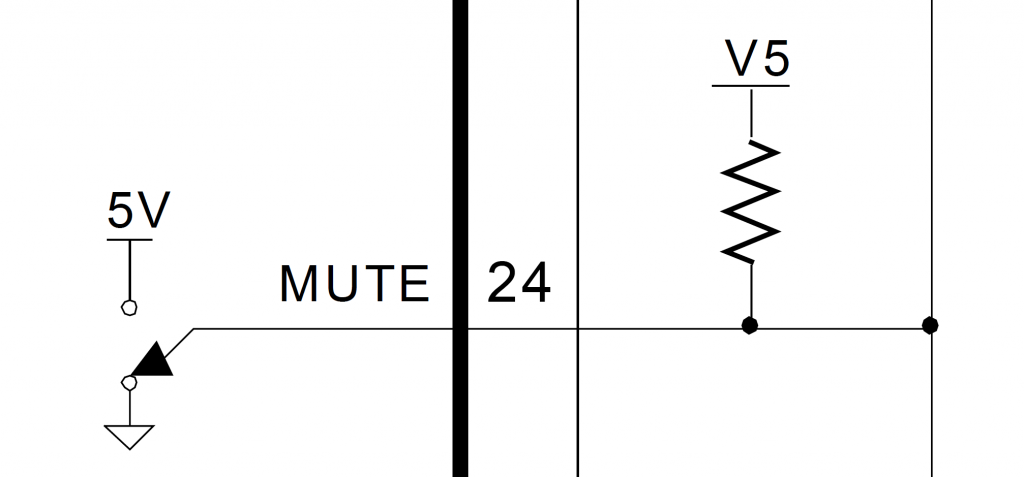
Just in case if people are wondering. The L01 chip’s datasheet is here:


To make a dedicated Raspberry Pi Zero device to run this script (program_toner) repeatedly on boot, I made a script loop_program_toner that runs the same program as infinite loop. I added 5 seconds of slow flashes after a successful write. To prevent the program from retrying too fast (sucking up computing resources) when there’s nothing connected to it, I wait for 1 second between each retries.

#!/bin/bash

if [[ $EUID -ne 0 ]]; then
  echo "Needs root permissions. Try sudo"
  exit -2
fi

while :
do
  bash "${BASH_SOURCE%/*}/program_toner"
  if (($?));
  then
    sleep 1;
  fi
done

There are a few steps needs to auto make this automated:

  1. Have a user account dedicate to autorun the program on boot. In the example here, we’ll use Raspberry Pi’s default admin account
  2. Auto-logged on by running sudo raspi-config, select (1) System Option > (S5) Boot / Auto Login > (B2) Console Autologin
  3. Bless the said account with password free sudo rights: Run sudo visudo and add this to the end (replace admin with something else if you chose a different username)

admin ALL=(ALL) NOPASSWD:ALL
  1. Call loop_program_toner in ./profile (startup script). Can place this at the bottom if your package folder is ~/spc250dn :
sudo ./spc250dn/loop_program_toner

The path can start with . or ~ because you are starting with at home folder anyway.


EDIT (2023-11-1): Linux people lack the backward compatibility decency again! They changed /led0 and /led1 to /ACT and /PWR under /sys/class/leds and they don’t have the decency to put in a symbolic link so old cold won’t break! WTF!

Do they have an idea how many code they’ll break and how many man hours they will waste the world to discover this breaking change when updating the distro? Non-caught exceptions just fall through and shows up as mysterious error messages!

If you want people to get the memo and change their code to match a more sensible notation, feel free to put in a warning stub, but hell no to just flip a switch and watch the world scream! This is apparently not a difficult decision to make when adding backward compatibility would be a huge project because of some catch-22 conditions!

ARM: dts: Standardise on the upstream LED names · raspberrypi/linux@ea14f14 (github.com)

Raspberry Pi Zero only has one LED which is /led0 (/ACT), so ignore /led1 (/PWR).

Loading

ATX Motherboard 433Mhz Wireless Remote Soft Power Button

I tucked away my PC a little away from my workstation desk and the power switch is located at an inconvenient location. I tried to keep the wiring minimal so I’d rather not wire a dedicated ATX power switch onto my desk.

Unfortunately my motherboard does not support turn on by USB keyboard, and I’m not ready to upgrade because I am using it to test PCI data acquisition cards and it’s the fastest one that has 4 PCI slots and they are hard to find nowadays.

I found a $2.5 wireless module on eBay that claims to switch LED lamps which works on the standard 433Mhz channel and it replicates momentary switch pattern and can operate on 5V (My motherboard is new enough to have 5Vsb from onboard USB header).

Initially I was tempted to get the built-in relay version, but I was worried about the current draw from 5Vsb and those are 12V relays., not to mention the footprint is much bigger (the one above is 22.5mmx 11mm x 8mm).

I thought I can figure out with some sort of BJT switch instead of using a relay that has a much bigger current draw requirement, but I realized it’s a pain in the ass because the output is ‘floating’ differential. The OUT- does not tie to the power ground (it’ll short out the unit when I tried to. That’s why I added quotes to ‘floating’ because it’s only relative to OUT+). I also measured OUT+ which is +5V with respect to power ground.

I tried to power a LED and it only works if current flows from OUT+ to OUT- so it’s really sinking current from source power to do that, and it’s unidirectional.

I’d just take a gamble and hook up with a 5V NO relay that I have around. Turned out it actuates with the 5Vsb from the USB header. I glued the relay to the back of the PCB and hook up a flyback/snubber diode (reverse biased) across the relay coil so the back EMF won’t fry my motherboard.

Seems like the transmitter-receiver pair is on momentary switch mode by default, so no addition configuration is needed other than pressing the learn button and immediately press the transmitter button to pair.

I wired a jumper extension cable (male – female) to the relay output from the middle as a by-pass since I’d like to keep the original power switch’s functionality (so it’s basically OR-ing between hardwired switch and the wireless remote 433Mhz switch)

Here’s an example of taking 5Vsb from USB header and tapping into the power switch jumper in Front-Panel jumper block:

Note that the PWR SW- pin is connected to the ground. Since I’m using a relay, the relay output is floating so the polarity does not matter.

Loading

Lepy LP-2051 Class D/T Amplifier Turn-off Pop Fix Mod

A few years ago I switched my stereo system (I’m using them as computer loudspeakers) to Class D because I was annoyed by the heat the professional (Class AB) amplifiers generate heating up the room (electricity bill aside).

I personally prefer the sound from Tripath amplifiers (started with LP-2020A and LP-2024A), which they called Class-T, but it’s really just Class-D with better PWM feedback mechanism. To drive bigger speakers with stronger bass, I bought a LP-2051 (50W x 2 RMS), which uses TP2150 (200W driver) + TC2001 (Audio Signal Processor) Tripath chips.

However, this amplifier has a very fatal flaw: it has a ridiculous loud turn-off pop! The system has speaker protection relays, so there’s no turn-on pop as expected as speakers are connected 3 seconds after switching on the power.

The turn-off pop bad enough that I was about to toss that in the trash as the amplifier fearing that it might damage by expensive and hard to get ADS vintage speakers. However Class-T chips are no longer produced and the TI Class-D chips for some reason just doesn’t have the clarity in the mid-range and high-frequency range I was looking for in Class-T amps, so I’ve decided to figure it out.

DO NOT TOSS YOUR Lepy LP-2051 Amp because of the loud turn-off pop!
There’s a simple way to fix it if you have a soldering gun, some wires AND a relay (normally open, 5V coil)!

Before I get to the solution, here’s a a few things I figured from observing the board which helped:

  • The power line is 19V (the unit won’t turn on until it reaches 18V, so the acceptable range is 18V~19V)
  • The unit draws around 1/3 of the turn-on power when the power switch is off. The switch is AFTER the power rail smoothing inductor and tank capacitor so they are charged.
  • Turns out the speaker protection relays are hooked straight to the 19V plug input BEFORE the switch (two channel’s relay coils are chained in series, then to the collector of a NPN transistor acting as a switch)
  • The 5V regulated (rightmost pin of 78M05 when viewed from top) is always powered even when the power switch is off.

[Failed] Attempt 1): was to disconnect the left/right speaker wires with 24V external relays switched by the front panel power switch (it’s passing 19V and 19V is enough to activate the relay). The reason is that the power droop faster than the relay disconnect when losing power.

[Mixed success] Attempt 2): I have a big power capacitor 0.12F as external power smoother (initially used to fix huge transient power draw for huge bass transients like drums), which slows down the power droop when the power is switched off enough there’s no power-off pop. However, this solution is very clumsy as reasonably sized 0.022F capacitors won’t slow the power line droop enough to avoid the turn-off pop. This observation gave me the idea that it’s the power-loss detection circuit not reacting fast enough for the system to do the proper ‘shutdown’ procedures (muting the output or disconnecting the speaker wires).

I initially looked into expediting disconnecting speaker protection relay when the power switch goes to off position, but realized it’s already done in the transistor switch logic (cascaded NPN stages) that controls the speaker protection relay as I trace the circuits.

I started looking up the datasheet looking for built-in mechanism in the IC that mutes the amplifier as I switch the unit off (the unit is partially powered once the DC plug is in). Turns out there is: the mute pin is on TC2001’s pin 24 (MUTE):

TC2001, pin 24 is the mute pin (it’s active, aka mute, on high)
TC2001 Mute (Pin 24) has internal pull-up resistor

I tried flying pin 24 to the 5V regulated output (on 78M05) and it muted as expected. I didn’t really bother to check, but when I take out the jumper wire, it’s unmuted as expected (which contradicts with the datasheet description that floating is considered high/mute, so I assumed there’s other logic driving it low by default)

[Failed] Attempt 3): Use a NPN transistor like 2N9304 (and a potential divider to tap the 19V logic to 4.5V) to drive the mute pin (TC2001 pin 24) high (which means muted) when I power the unit off. The turn-off pop is still there because it turns out that there’s a 200ms delay for the mute pin:

So now the goal is to have mute activated (set to high) FIRST a little before the 19V power line gets disconnected. The timing order for turning on does not matter because the speakers aren’t going to be connected until after 2.5 seconds once it’s hooked up to the 19V source, it doesn’t matter what’s the logic transient logic level of the mute pin (it’s going to be NOT connected to the 5V when the SPDT power switch is ON steady).

Realizing that there the power switch acts the fastest, then the mute pin, with relay actuation being the slowest, and the power switch that came with the unit is a SPDT, I don’t even have to implement a timer to delay disconnecting the 19V line before it finishes muting. Here’s the winning solution:

I accidentally wrote 18V rail voltage instead of 19V. The unit works anywhere from 18V to 19V, so you get the idea that I meant the same thing.

I happen to have a Fujitsu/Takashimaya JY5H-K5VDC reed relay which happens to be a NO (Normally Open switch) which happens to fit the design like a glove. Here’s a picture for the experimental (working) hook up that the turn-off pop is completely gone:

On the board, there’s actually a reserved spot for a on-board jumper in place of the supplied/installed SPDT switch. Those are the two red wires rerouted to the relay switch.
(FYI, the bottom node goes to 19V of the DC jack, the top node goes to the rest of the 19V circuit)
The 5V line is the green wire. Goes to the common/middle pin to be switched by the SPDT switch.
The mute pin (pin 24) is the brown wire. Goes to the furthers/longest pin of the switch
Ground is the black wire. Goes to any one side of the relay coil
The shortest pin of the switch goes to the other side of relay coil. I soldered it directly to the relay pin

Completed mod after cleanup:

Overview

There’s a few cleanup that I did:

  • I hot glued the relay on the two hard switches as they are not near any heat sources and mechanically stable
  • I stole the ground (going to the coil) from the nearby C5’s ground pad (C5 is the moderately big 470uF SMD cap nearby).
  • The old right-angled hard switch’s pins were lifted from the board by bending the pins straight.
  • The utmost pin/pad (leftmost, closest to the power plug) for the switch is not connected anywhere else on the board. It was a dummy as the SPDT switch was only used as a SPST switch. Good for me so I can solder one of the 3 pins there for mechanical support (otherwise we’ll twist the front two dummy solder joints for mechanical stability when we toggle the lever repeatedly). I chose to bend the middle pin to solder it to the board because the other two are either too far out or too short.
  • In summary, furthest SPDT switch pin goes to mute pin, the middle is the 5V regulated rail to be switched between the mute pin or the relay coil. The shortest SPDT switch pin goes to the coil. The rest are obvious

Here’s the finished mod with different angle shots for you to see the wiring:

Given the amp itself is cheap (but it’s really an excellent bang for the buck: clear sound, solid bass, class-D efficiency, small size and light weight), those who are not that electrically savvy might not be inclined to do that mod. If you are going to throw it away anyway, please send it to me (I’ll pay for postage).

It’s a very very simple mod that any beginner electronic hobbyists or an electronics student might be willing to do it for you with the instructions here for a small fee. Basically it’s just some wires and a relay and some good solder wick (or if you have a nice desoldering pump, it works fine too).

I typically don’t take petty service orders (under <$500), because of all the hassles shipping back and forth, opening it up, putting it back, and keeping records for the IRS, plus the liability risks. So please find a kiddo, hobbyist or tech to do it.

Loading

Handmade Powerful 100W flashlight

I had an old LED COB light that the power conversion circuit failed, so I decide to gut it and turn it into a lantern / flashlight with a spare 6V sealed acid battery, using a simple DC-DC (boost) converter board.

The 6V lead acid battery eventually died so I converted the unit to accept 6V~12V from outside. The whole lanter was made from whatever leftovers/excess materials I have in my lab, including a PC fan I got for free after rebates years ago. The case is made out of the case for a roll of lint-free alcohol wipes.

Loading