The firewall rules in MerlinWRT just quit working so the table I entered doesn’t do anything. Seems like other people had the same problem too. So if you just use the WebUI, it’s either turning the firewall all on or all off.
There’s a twist in configuring the firewall with iptables in routers: the instruction you got on the Internet often append the entry to the end of the table in the section (they use the -A switch) and they didn’t explicitly tell you that’s what they are doing and what the implications are.
Turns out when you enable the firewall in the router, it enters a table of DROP ALL lines, which is supposed to be a catch all after all the exceptions you spelled out! You are supposed to enter the exceptions BEFORE the default entries set by the router, not append after, so the packet you want to accept gets fished out before it reaches the catch all (drop all) entries entered by the router automatically when you turn on firewall. So the solution is to replace the -A (append) switch with -I (insert) switch
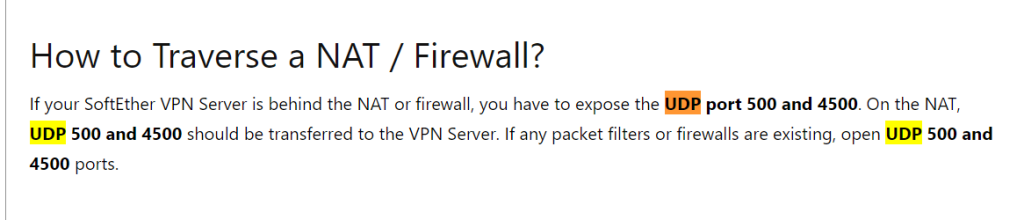
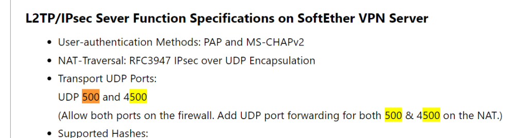
As for putting SoftEther VPN on MerlinWRT, here’s the commands to type in SSH to add the firewall rules to open the port, which is what the broken WebUI interface was supposed to do:
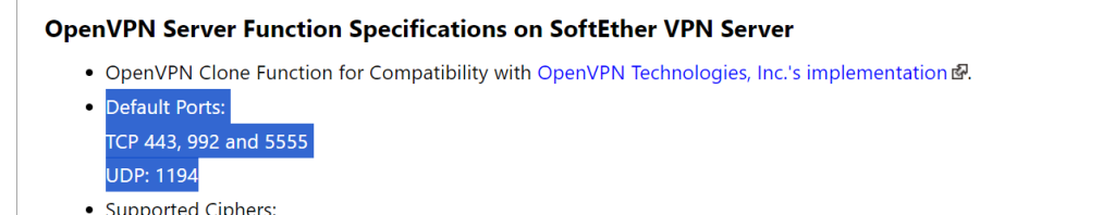
This line opens SoftEther’s standard ports 443,992,5555,8888, all TCP only.
Don’t even think of using iptables-save as the router do not have persistent storage other than /jffs or USB. I suspect iptables-save merely writes to RAM disk so the changes will be lost on next boot.
You’ll need to put this line in/jffs/scripts/firewall-start script instead. If this is a new file, make sure you chmod +x /jffs/scripts/firewall-start to make the file executable.
Well it’s not too bad of a design after-all since it’s a mess to fish out the iptable lines you want to delete, so keeping your changes in a file to be loaded with the firewall on boot is a smart move.
If all your devices downstream that you forward incoming traffic to (aka servers) has firewalls, the built-in firewall mainly protect the router itself, so if it gets too frustrating, it might not be too big of a deal to turn the router’s firewall off.
There’s also another weird behavior that if the port is firewall blocked, the server admin program intermittently still connect but it connects to a blank state server (blank config). WTF!
Wired USB Keyboard/Mouse to Bluetooth bridge (HID Relay)
Year ago I was so desperate to convert my beloved mechanical keyboard to wireless (most built-in ones do not have the kind of right tactile feel I wanted) so I was damn close to building an embedded wireless HID/keyboard on my own (there’s a Hackaday Tutorial for HC-05). Now Handheld Scientific makes it.
I was puzzled by why my dd-wrt router behave erratically each time I change the “Start IP Address” in DHCP leases to an upper range and I just figured out why.
I hate the user interface of dd-wrt with a passion, but it’s the only open source firmware for one of my routers that signed Broadcom’s close source NDA to get its driver SDK so I’m stuck with it:
Ugly as fuck
In the bad old days people think it’s a good idea to make 4 little edit boxes for IP addresses than checking if the input conforms to the IP address format with dots. But it cannot detect ‘.’ keypress and jump to the next box (use Tab instead). e.g.
Inconsistent state possible
Start IP address, which is dependent on Local IP Address, is not updated/reflected until you press “Save”. This means every time you make a change, you need to hit “Save” immediately so other dependent settings will make sense before you start editing them.
Features are arranged/grouped like config files
This is bare minimum effort on UI dev, which is not much better than going to linux prompt and edit the config files.
With config files, at least we’d be more careful and try to understand what each key-value pair mean and their relationship map. This lousy web admin UI interface gives a false impression that non-developers knows what they are doing, so it turns into a puzzle that we’ll have to google the answer for every fucking basic application.
Using the web UI instead of editing the config files feels like programming in assembly as an improvement over programming in raw machine code. It’s begrudgingly painful.
One example is the grouping for wireless radio. For most considerate web admin interface, the SSID are grouped logically with your WiFi password, but in dd-wrt, you set SSID in “Basic Settings” and the WiFi password under “Wirelesss Security”. Make sense for the programmer to decouple the radio from the access control (group by features), but it’s not application/use case oriented (group by radio interface), thus it frustrates users.
Non-intuitive (less common) presentation
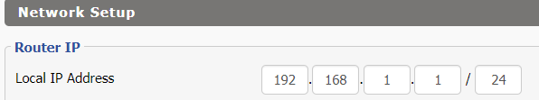
As described above, out of developer’s convenience, dd-wrt’s web admin UI just do everything that makes beginners’ life miserable or just throw them off. e.g. Windows users are used to specifying the subnet mask in quad-dotted notation like 255.255.255.0, not the CIDR notation like /24:
Confusing names
The names are often too terse that creates confusion with similar named features in a lot of places. e.g. “Wireless GUI Access” does not mean the welcome page for your Guest network, but whether the wireless client have access to the Router Administration‘s Web UI!
It’s probably a few minutes of extra thought to call it “Allow admin web UI: Yes/No”
Another example is AP Isolation, which is under Advanced settings tab for each radio:
Is this isolating APs in a mesh or isolating clients connected to the AP from each other? Turns out it’s the latter! Just say “(For this AP), allow connected wireless clients to talk to each other on the same network: Yes/No”. I think it’s a common use scenario that the regular users should be aware of and shouldn’t be stowed away with obscure radio/PHY-level tweaks (settings aimed for hackers).
Overloaded names
The admin web UI is littered with overloaded names/terms which means something completely different depending on context (like the settings 2 lines above). For example:
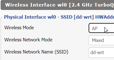
Access Point (AP) mode
The SSID here is the SSID of the Access Point (Wifi host. AP station accepting wirelesss clients)
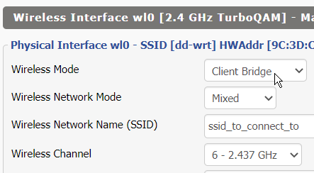
Client/Repeater[Bridge] Mode (all involves the dd-wrt router connecting to certain AP station/SSID)
The SSID here is the SSID where the Client/Repeater-Bridge/Client-Bridge is attempting to connect to that contains the uplink/WAN!
WTF?! The dialog box looks exactly the same despite the wifi section is acting like a completely different device! What the fuck is “Network Configuration: Unbridged” for a Client Bridge?! HELP!
Unchecked invalid combinations that crashes!
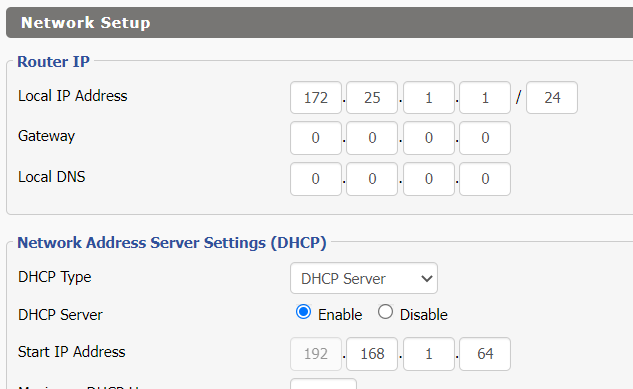
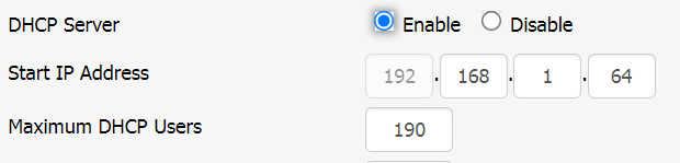
This is the most frustrating behavior and should be considered a bug. I wasted days resetting my router over and over and it keeps hanging randomly after I change the DHCP server’s starting IP address. This is the default out of the box settings:
Default DHCP settings. End IP Address is 192.168.1.253
End IP Address = Start IP Address + Maximum DHCP Users – 1. They probably chose this number to reserve 192.168.1.254 for static IP (like some admin page of other devices). 255 is broadcast IP so of course it shouldn’t be assigned
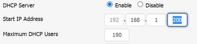
Moving the the “Start IP Address” up without adjusting “Maximum DHCP Users” accordingly will make your router behave erratically because the DHCP will try to lease IP out of range!
This will corrupt your router’s memory!
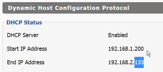
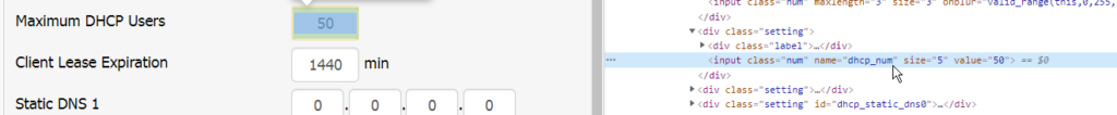
The End IP Address is displayed on Status -> LAN -> Dynamic Host Configuration Protocol -> DHCP Status. And here’s the WTF moment:
The End IP Address is now in a different subnet from the Start IP Address! I’m using /24 so 192.168.1.X is different from 192.168.2.X.
From the web page, the attribute name is “dhcp_num”
This is the code that shows the derived ‘End IP Address” shown above
I don’t know how it is coded, but if this number is computed in a low level way, chances are it’ll write garbage to the memory (for example if the number is used as an array index). I think normally it’d be checked in any not-so-shitty user interface so the invalid state/condition won’t propagate down the code and hang the router. But in my case it did. If I just reboot the router without resetting to the defaults, it’d just hang again after a few interactions (like moving between a few pages or applying a setting).
In any case, this check must be done at user level as even if the low level code say, quietly sets a valid default value when an invalid range was ‘entered’, it’d only surprise the user and make it even harder to troubleshoot. This UI bug is even less excusable as it’s more natural to have users enter the (Start, End) instead of (Start, # of slots). Probably takes half an hour more in coding to layout the UI code to enter ranges (add 4 boxes for quad-dotted notation for End IP and check them instead of just 1 box for # of DHCP leases), but making the user to do mental gymnastics and punish them by if they did it wrong is just outright terrible.
FreshTomato has quite a bit of learning curve, but at least it try to do something that’s sensible for users for common scenarios instead of sticking strictly to how the code/config files are written at developer’s level.
DD-WRT is powerful but the UI suck big time, not because the features overwhelm less tech savvy users, but it’s purely unnecessary torture and pain even you know why it’s done that way. It’s web UI is as helpful as editing the text config file raw.
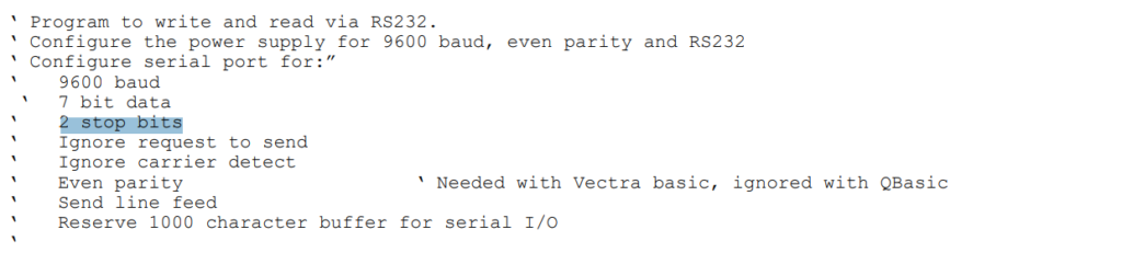
Turns out Agilent instruments do not use the same defaults for the RS-232 in their instruments.
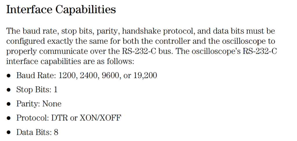
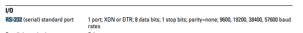
54600 series uses 1 stop bits (most common):
RS-232 modules used in old 54600 series54620/54640 series (newer 54600 series)
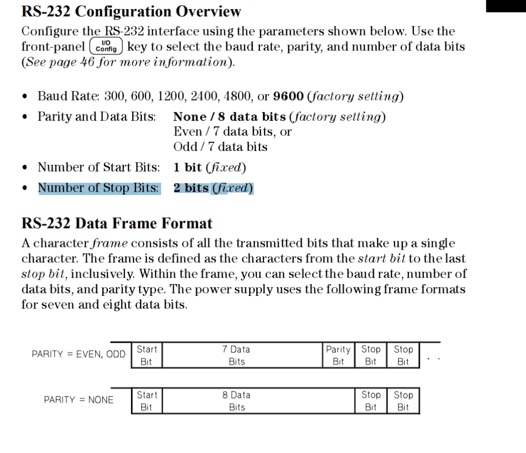
However other bench instruments such as power supplies (E3640 series 663X series) and 33120A arbitrary waveform generator uses 2 stop bits (fixed regardless of parity), which is usually NOT THE DEFAULT for most terminal clients:
E3640 series and 33120A’s RS-232 configuration. Parity only trade away one data bit, so it does not affect stop bit663X series powers supplies’ programming manual aren’t explicit about that except in code example
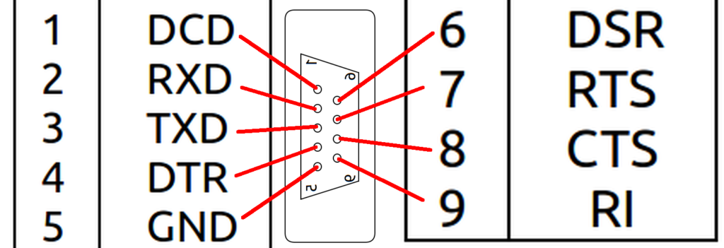
The pin ordering for RS-232 (DB9) pin is sequential is row-wise (the long side is a row) while the IDC-10 (ribbon cable) header is column-wise (zig-zag pattern).
This might be a little confusing because geometrically, they are in-place on both sides (you can overlay the pins of DB9 on top of IDC-10 and they align perfectly, except pin 6-9 was lowered by half a notch on the DB9 side). I am writing this post so nobody waste their time separating the wires in a ribbon just to find out the DB9 was designed so it aligns with the flat ribbon cable perfectly.
If you split the table on the right in half (cut after pin 5) and place pins 6 (DSR) ~ 9 (RI) on the right, you’ll see it align with the IDC10
1
DCD (Data Carrier Detect) Check if connection dropped
DSR (Data Set Ready) DTR-DSR Handshaking
6
2
RxD (Receive Data)
RTS (Request to Send) RTS-CTS Flow control
7
3
TxD (Transmit Data)
CTS (Clear to Send) RTS-CTS Flow control
8
4
DTR (Data Terminal Ready DTR-DSR Handshaking
RI (Ring Indicator) For phone rings
9
5
GND (Ground pin)
– (Not connected)
10
Rearranged DB9M RS-232 to align with IDC10
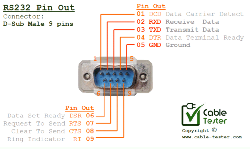
Cable-tester.com has a clearer annotated picture that matches the physical mapping above:
http://www.cable-tester.com/rs232-pin-out/
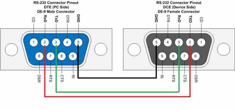
Note that the tutorial itself has Tx(D) and Rx(D) reserved it was building a null modem cable and they skipped all the handshake lines. I’m doing a straight cable (which should be done for internal board header cables where the DB9 socket is male, hence DB9M).
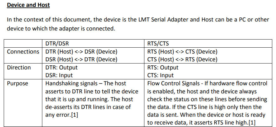
The DTE/DCE might be confusing. Hope these properties can help people make sense out of it (so you can figure it out in your head confidently instead of randomly trying null modem adapters till it work)
DTE device (colloquially ‘computer’) has the pattern as shown in the pictures above (receive pins above/before the transmit pins), which is usually the computer end and the port/socket is male. Think of it as the ‘driver/master’ (though it’s arbitrary)
DCE device (colloquially ‘modem’) reverses all the sends and receives of the DTE. Can think of it as the ‘receiver/slave’ (though it’s arbitrary). It’s usually the modem and the port/socket is female.
For DTE-DTE (like data transfer between two PCs), the send lines on one side should go to the receive lines on the other side. A null modem cable that swaps the send pins with receive pins. You can think of it as making one side DCE. Given that the topology is symmetric, it’s up to the software set up to decide which side is the initiator/client (master) and which side is the reactor/server (slave)
The handshaking (optional) and flow control (optional) lines also have their initiator/reactor roles reversed with null modem cable.
It turns out the direct geometric mapping (IDC male pins match the relative locations of the DB9 male pins) mentioned above is the less common type of motherboard header configuration. IDC ribbon crimp-on DB9 headers like this:
has to follow the above geometric layout since the pins cannot be remapped (so it has to follow the ribbon order). The soldered version looks like this:
https://store.cwc-group.com/lowprldb9mat1.html
However, the more commonly seen soldered RS-232M to IDC10 header uses a transposed configuration (which DB-9M pin numbers matches IDC-10 pin numbering EXACTLY despite one is row-major and the other is column-major), which has nothing to do with the IDC10 pin layout mentioned above.
https://store.cwc-group.com/lowprldb9mat.html (I don’t think it’s a good idea to call it ‘crossed-config’ like CWC did. It almost mislead me to think it happens to swap the roles of Tx and Rx. I did the mapping on paper and it didn’t make any sense. Let’s call it ‘transposed-configuration’)
The crazy thing about the existence of these 2 pin layouts is that there’s no easy way to tell which pin layout/mapping it is until you open the connector up and inspect the solder joints! Taking a pin and probe it with a multimeter is more work than taking the screw posts out and disassemble the connector.
So if you just buy some old scrap parts that came with old motherboards, this might confuse the heck out of you until you tested the pin mapping with a multimeter and realize things doesn’t add up!
Note to self: just open the DB9 side up whenever I see a DB9-IDC cable and mark the configuration on the DB9 end directly on the cable!


![ฅนบ้ายอ: [34+] Db9 Male And Female Connector Pinout](https://external-content.duckduckgo.com/iu/?u=https%3A%2F%2Fsharvielectronics.com%2Fwp-content%2Fuploads%2F2020%2F09%2FD-SUB-DB9-9-Pin-Male-Connector-To-IDC-Female-10-Pin-Flat-Cable-30CM_1.jpg&f=1&nofb=1)