TDS Color CRT Driver Repair (700 series): all by sniffing TDS 784A with Garbled Display (Driver 671-2373-389-1344-01 / 678-1402-07)
When old equipment’s fail, they do fail in waves, depending on the failure modes induced by the original design. Last week when I turned on a TDS 784A in my inventory check, something smelled bad and the display was garbled (it has displays, but straight lines turned into wiggles).

I already replaced the caps for the processor board, keyboard and RS-232/Parallel Port module preventatively and the unit used to work fine. So it boils down to either the power module or the CRT driver.

Despite it’s unlikely to be the power module (didn’t feel any fan speed changes, display brightness changes, or hiccups in power), I used my nose to make sure there’s no burnt electrolyte smell from the power module. Indeed there wasn’t.

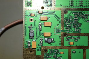
Sniffing can be a very valuable tool to repairs. The smell came from only one narrow area of the board so I limited it to 3 capacitors next to each other:

I took them out and cleaned the PCB and noticed that the wipes has a bit of green and black stuff on it. That’s how I can tell a capacitor just peed all over itself. The culprit is C321 and C323.

(EDIT 2023/05/18: I just noticed my TDS684B might have leaked C328, the biggest 100uF 50V cap right in the trio instead. I confirmed this by seeing the transistor TIP31C at Q330 turned green like it got mosses and the 3 pins fizzed out while the 3 resistors next to C321 stayed shiny. Strangely, despite physically C328 looked the most impacted, I only smell the familiar burning electrolyte scent when I desoldered C321 and C323 but not C328, so I replaced all 3 instead. The ESR for C328 is still low so despite visually it looks like C328 is the culprit, the leak could have just have electrolytically migrated to Q330 and dried up. Dried up electrolyte is hard to catch. That’s why I didn’t wash the board last time and only cleaned the surrounding areas with rubbing alcohol. Not again. ‘Power-washed’ it with dish soap using waterpik, rinse, load it with 99% alcohol and blow dry with heat gun set on low. The TDS684B used to work in my possession, so the leak must be recent and the signs not so obvious. My previous experience definitely helps because it’d be impossible to troubleshoot with visual inspection as the leaked caps didn’t bulge).

Note that the component layout for this color CRT driver, 678-1402-07 (the board has silkscreen saying 671-2373-389-1344-01) does not match the component locator I have with my TDS 544A schematics. Nonetheless, it’s nearby if you look around.

Just to confirm the capacitors I took out are the culprit, I used an LCZ meter as an overkill ESR tester to test them:

2.4Ω ESR for the 10uF (C321)

1.5Ω ESR for the 22uF (C323)

ESR for these two caps should be at the order or milli-Ohms if they were any good. I took the one next to the two offending capacitors out to test it, and the ESR looked OK so I put it back. The true reason is that I don’t have that capacitor value on hand at the time of writing, but that also helps to narrow down the true cause.

I replaced these two capacitor and the display worked correctly (not garbled). The brightness is a little bit high which can be adjusted down.

EDIT 2023/05/18: C5 (100uF 50V) at the corner of the board leaked. There’s a clear yellow film around it and it corroded the pins of the Q10 next to it.


The next problem is that the shutter color changes out of sync back and forth at a slow then fast rate till it gets stable after warming up for a while. I did a lot of troubleshooting, changed a bunch of capacitors and transistors and shutter board, but no avail. In the process, I smelled electrolyte evaporating with the flux and I decided to give the board a full wash with dishwasher detergent and waterpik (then dry the big part with a leaf blower, spray with 99% rubbing alcohol to the water out and left it dry). Bingo!

Lessons learned: do not leave the electrolyte leaks on the board even if it’s an old fashioned single-sided through-hole with relatively simple thick traces. I thought it’s not going to matter until I see visible corrosion, but I was wrong. Could it be the electrolytes left on the board forming weakly conductive paths that disappears when the unit warms up (the electrolyte dries up)?


In the process of replacing all the electrolytic capacitors on the board, I smelled fumes mixed with electrolytes in some areas (other than the two above). However, I didn’t record it because I measured the ESR for each capacitor that I pulled and compared to the ones I’m about to put in.

In addition to the two capacitors mentioned early in this post, here are few capacitors that the ESR of a new part is significantly lower, which might be first places to consider replacing before recapping the entire board. They are all measured at 1V, 1kHz:

Part Capacitance Voltage Rating Pre ESR Post ESR
C334 10uF 25V 2.8Ω 1.7Ω
C50 2.2uF 250V 11.4Ω
C12 22uF 100V 1.4Ω 0.6Ω
C181 470uF 35V 160mΩ 44mΩ
C182 1uF 50V 20Ω 13Ω

Nonetheless, the only useful technique that contributed to this board being repaired is finding out where the smell comes from. The rest (reading at schematics, measuring voltages, checking waveforms on an oscilloscope, swapping out parts) are all red herrings.


In the process of troubleshooting with schematics, I also noticed that the schematic for the old TDS 544A color CRT driver is actually pretty much the same (including component numbering) as this newer board 678-1402-07 while I was troubleshooting with it.

Looks like the component layout was slightly shifted to make room a different batch of flyback transformers (there’s a riser board for the flyback transformer in 678-1402-07 used in 754A/784A). Although the component locator sheet isn’t exact, the components are within 1 inch of what’s found in TDS 544A CRT driver’s component locator. No biggie if you don’t have the schematic for the newer color CRT drivers. Just look around and pay attention to the silkscreen. Common sense will lead you to the right part.

Loading

HP 3560A Handheld Dynamic Signal (FFT Spectrum) Analyzer Teardown (A2 board)

I was repairing a HP 3560A that does not start up at all. The system is very modular that there are only 3 main units: LCD/keyboard/DSP board (A1), Main Processor board (A2) which manages power sources and contains the backlight inverter as well, and the analog section (A3).

Obviously the first thing to look for is where the power is managed, which is the main processor board (A2). I bought another unit (with a different defect, i.e. it boots) hoping to use it as a reference but to my surprise, the A2 board is slightly different! In fact, the LT1120 voltage regulator that I’m seeing unusual pulses in V_out pin (should be flat) is not even there!

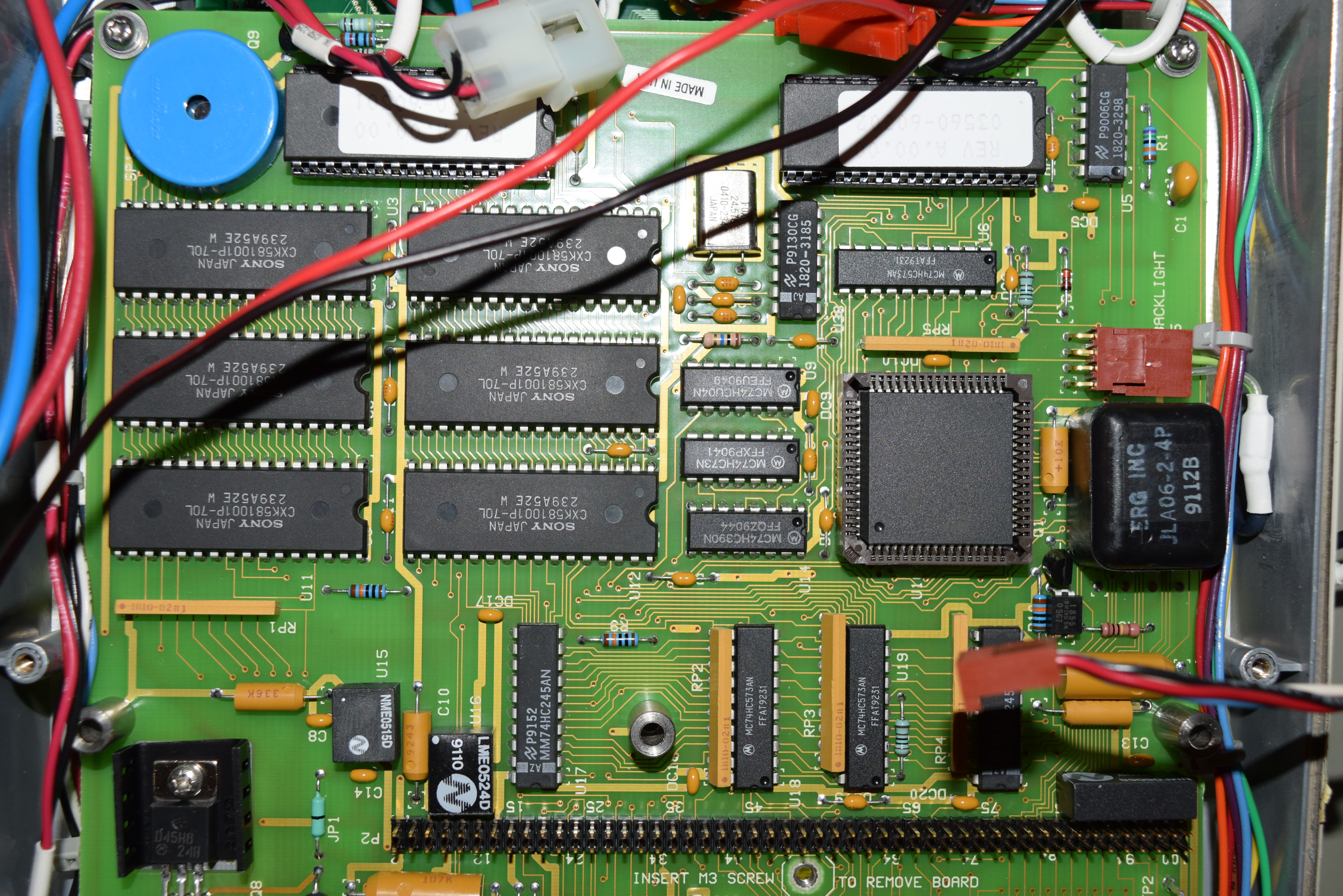
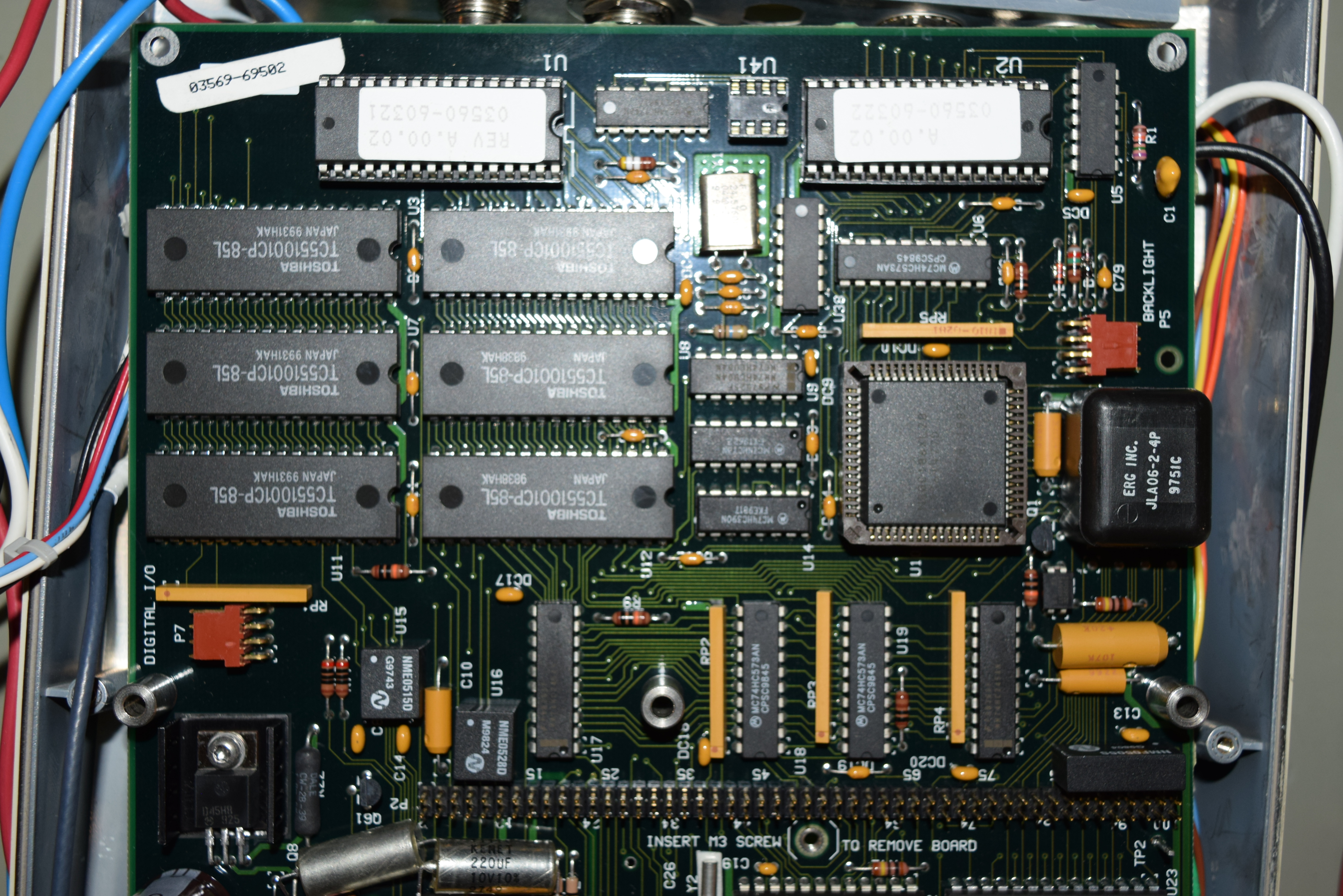
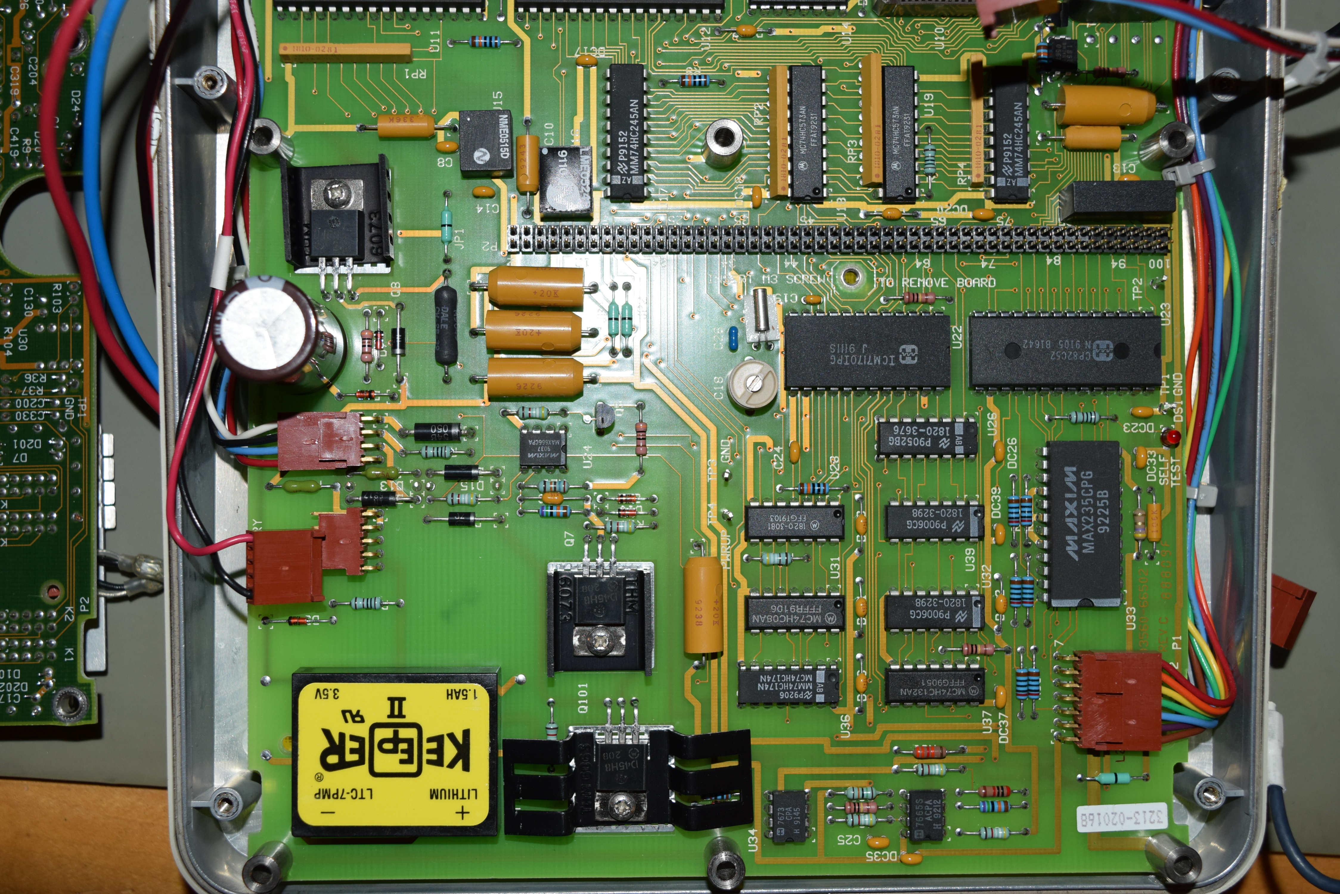
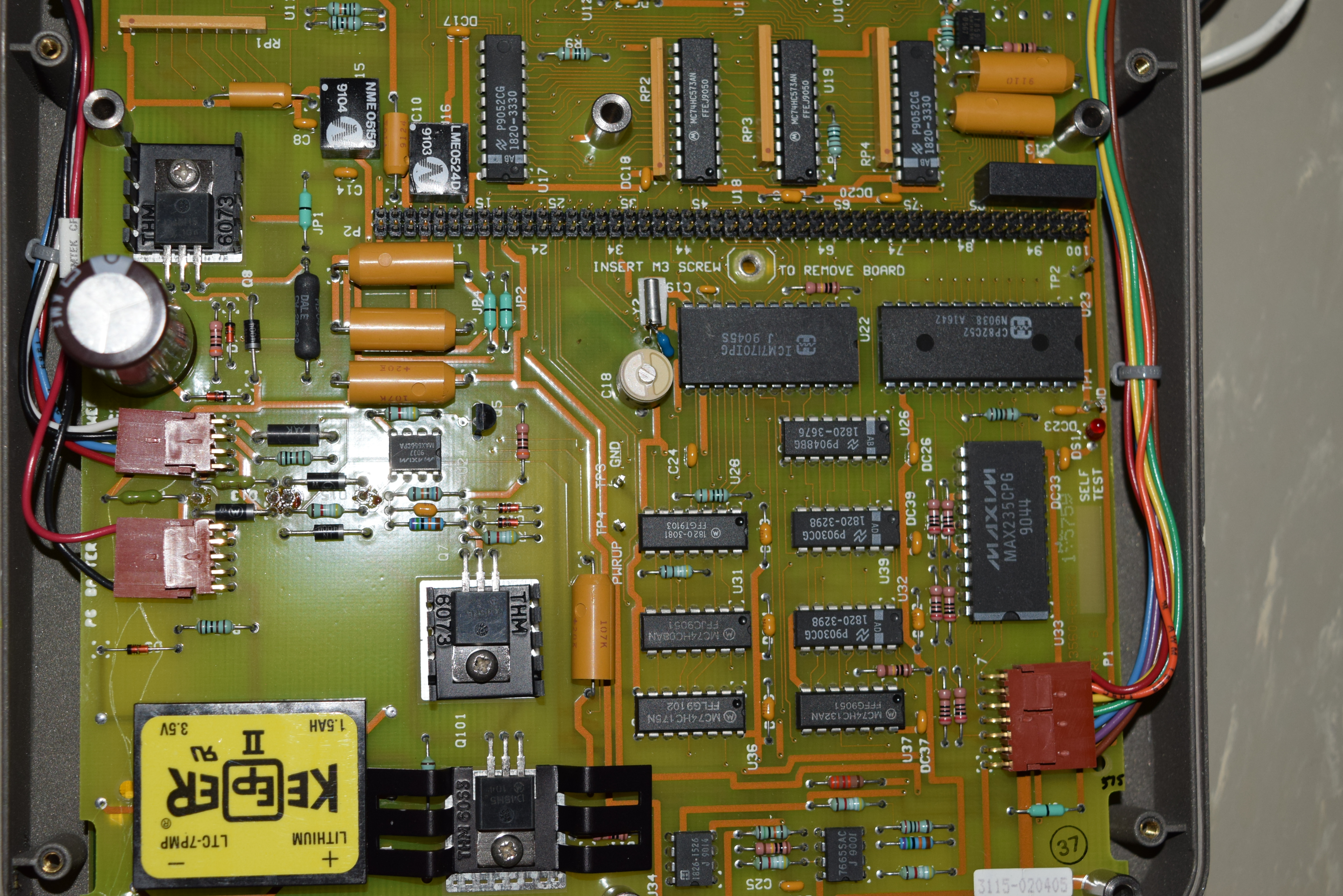
I’ll save the repair story for another post, but for information preservation purposes, I took pictures of the two different revisions of the A2 assembly from 3 units, shown below:

  • New: 03569-66502 Rev B
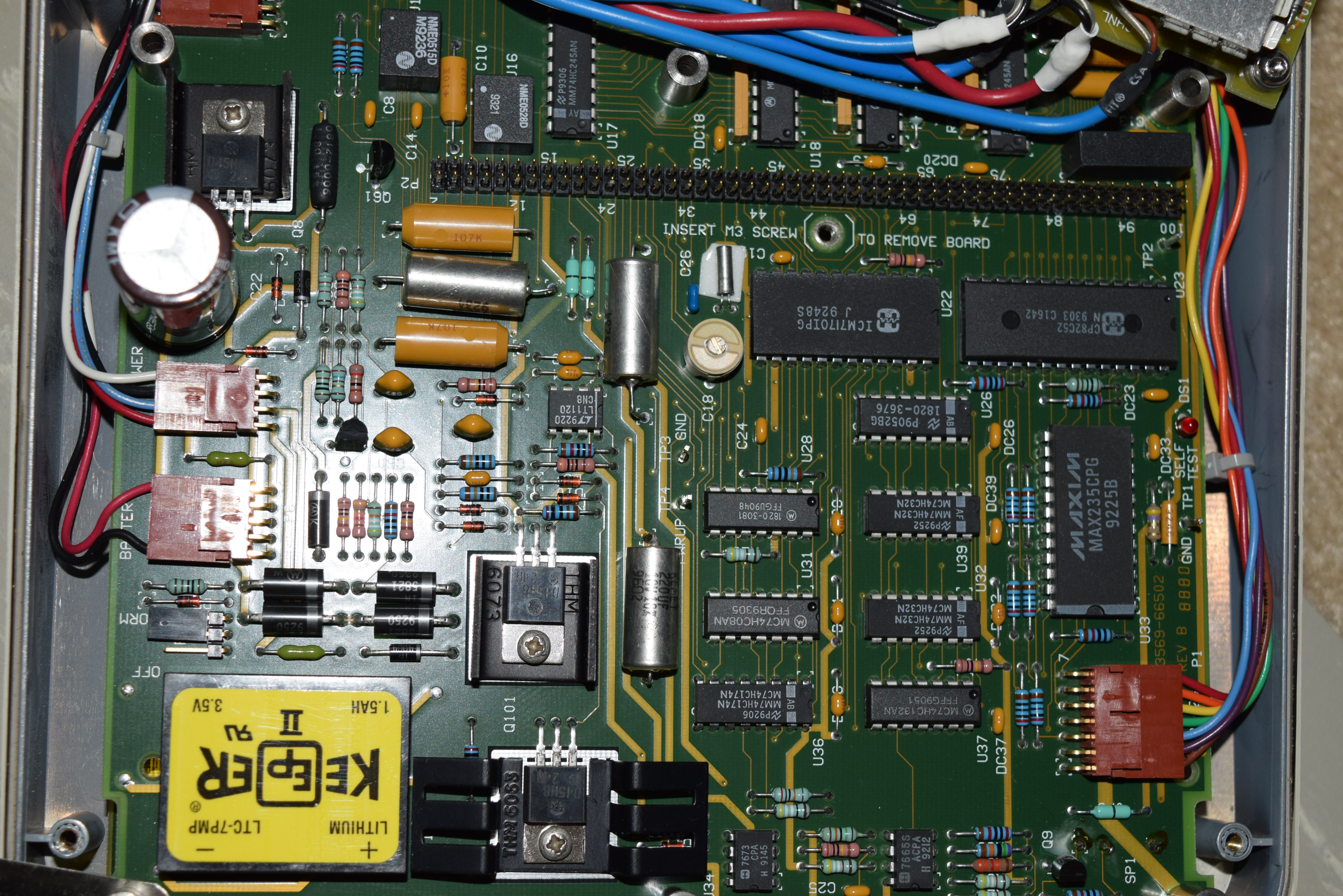
  • Old: 03560-66502 Rev B, Rev C

The top part of the board is essentially the same. The new board uses Toshiba TC551001CP-85L while the old board uses Sony CXK581001P-70L for Static RAM. They are likely pin compatible and it’s just availability differences. (Ignore the randomly placed caps at the bottom of the new A2 board. I desoldered them to test if they are good).

If you pay close attention, at the top of the new revision board, it has an unpopulated DIP-8 socket and an extra 74HC174N chip, and an extra digital I/O port at the mid-bottom left edge below the SRAM. They are reserved for 3569A (a better version with a noise tracking generator) as it uses the same board. The old revision A2 board works for 3560A only. It’s a topic for another post.


The bottom part is quite different. The classical 4-diode full-bridge rectifier on the new board is not shown at the main side of the circuit board for the old A2 assembly. The new board looked much denser.

Most importantly, the old board uses MAX666 as the 5V voltage regulator while the new board uses LT1120. The pinouts are different and chip features varies a little bit, so the power management section is not topologically identical.

There are no components on the back side of the new revision A2 board (they are both supposed to be single sided PCBs), but two diodes are squeezed in at the back of the old revision A2 board, and there’s an extra resistor flyover:

My suspicion is that the diodes are intentional as there are specific through-holes for them (most like they other half of the bridge rectifier), but the resistor is an after-spin rework.


Finally, for information preservation, I also took pictures of the old A2 board (03560-66502 Rev B) from another unit I have:


If you consider the relative ease of use for less computer savvy people, 3560A/3569A is versatile yet designed specifically for the most commonly used measurements in acoustic and mechanical vibrations. It’s still excellent value for what it offers despite it’s a made decades ago since it doesn’t overwhelm you with convoluted choices so you can gets the job done once you’ve setup your recipe.

HP has designed the unit very well, with the exception of the LCD screen which cannot be found on earth, all through-hole components on single layer board and well organized structure and silkscreen makes servicing a pleasure.

I can repair and rebuild 3560A / 3569A with new battery pack and clock battery. The hardest problem to track down is no-boot, and the hardest surgery to make is the backlight. I also know how to talk to the unit from modern computers as well, so data capture is not a problem. Call me at 949-682-8145 for  consultation.

Loading

HP 3560A Battery Pack 1420-0584

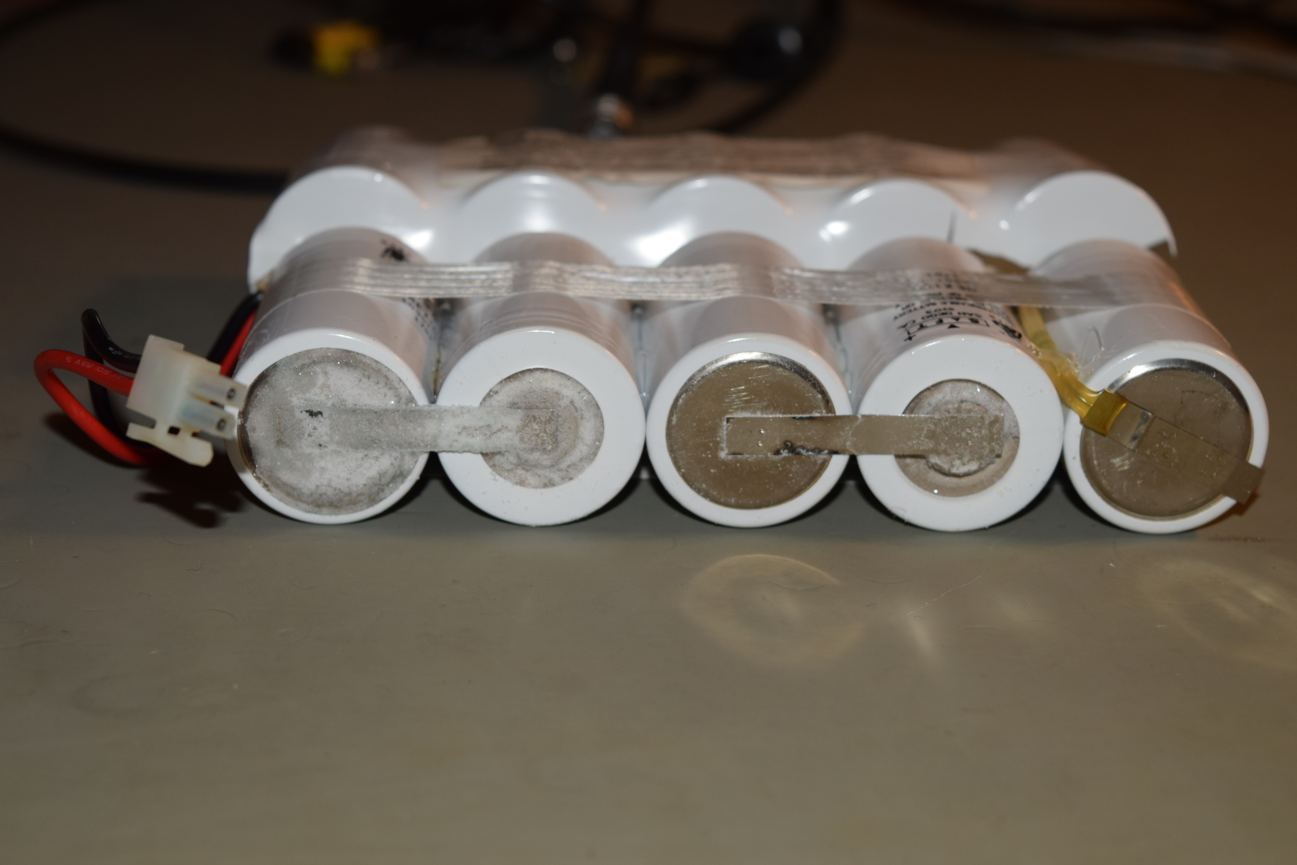
If you have an original HP 3560A sitting for years and haven’t changed the battery pack yet, it’s guaranted to be dead. Here’s the shell of the battery pack 1420-0584:

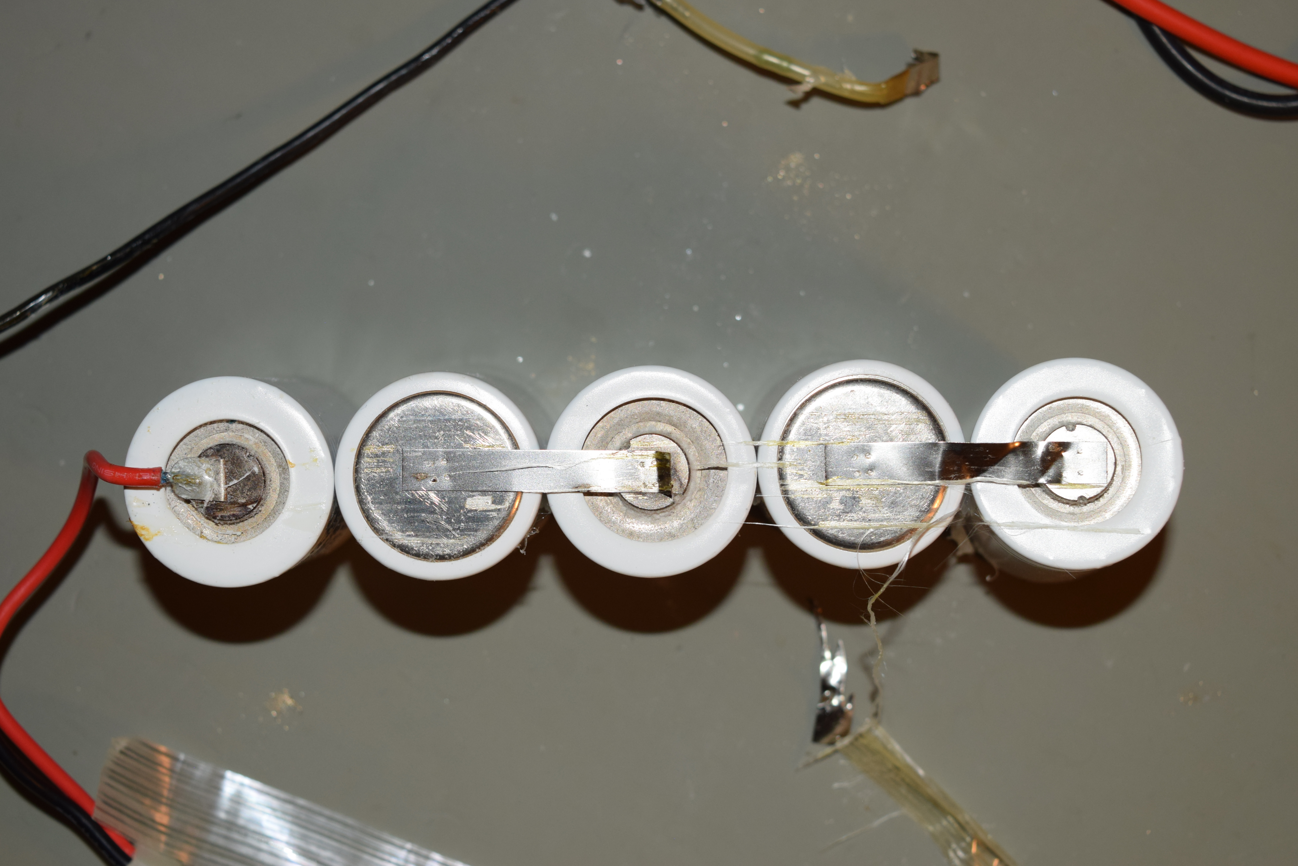
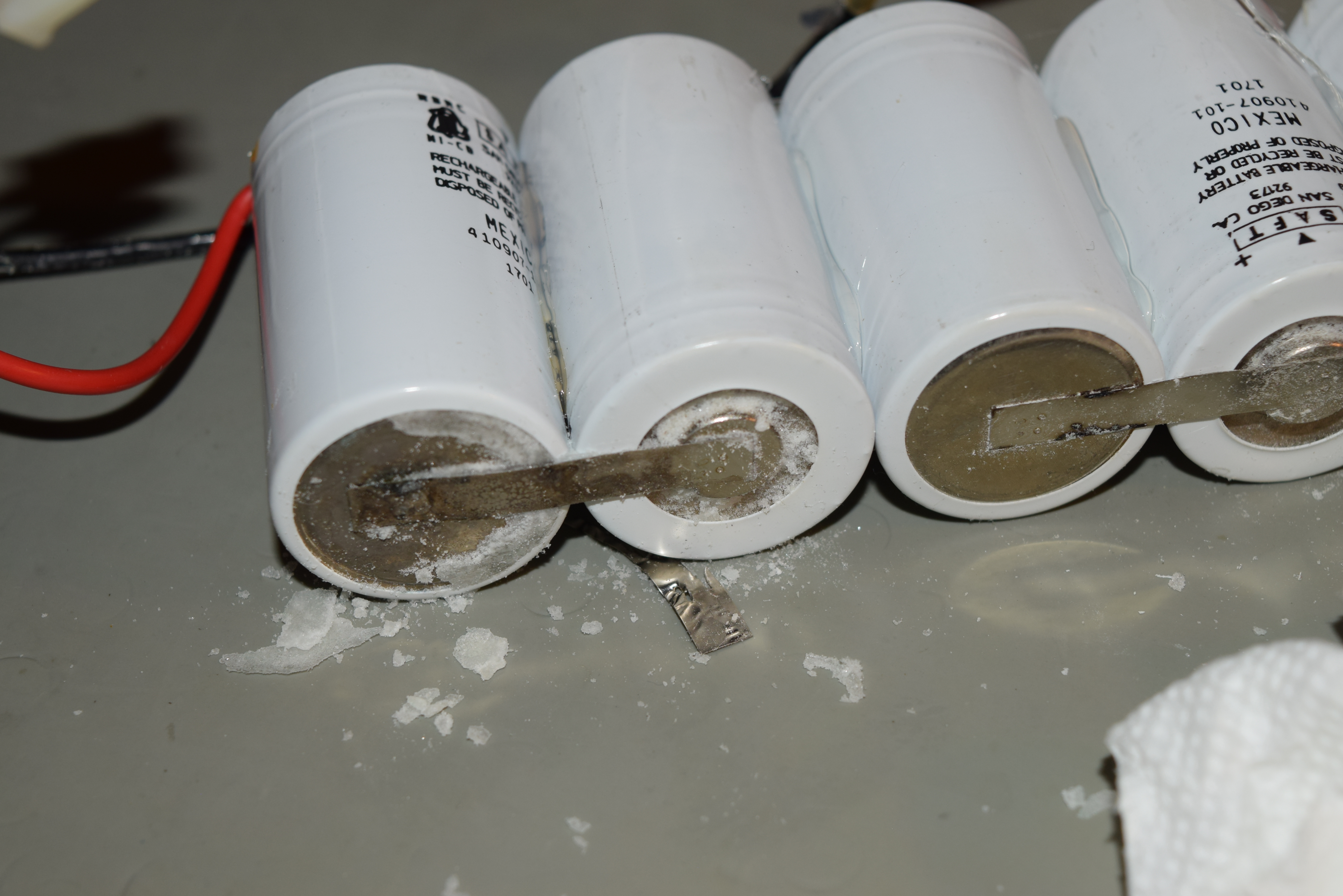
Just to give you no hope attempting to reused the battery pack, I dissected one of them and show you how much of a disaster inside it:

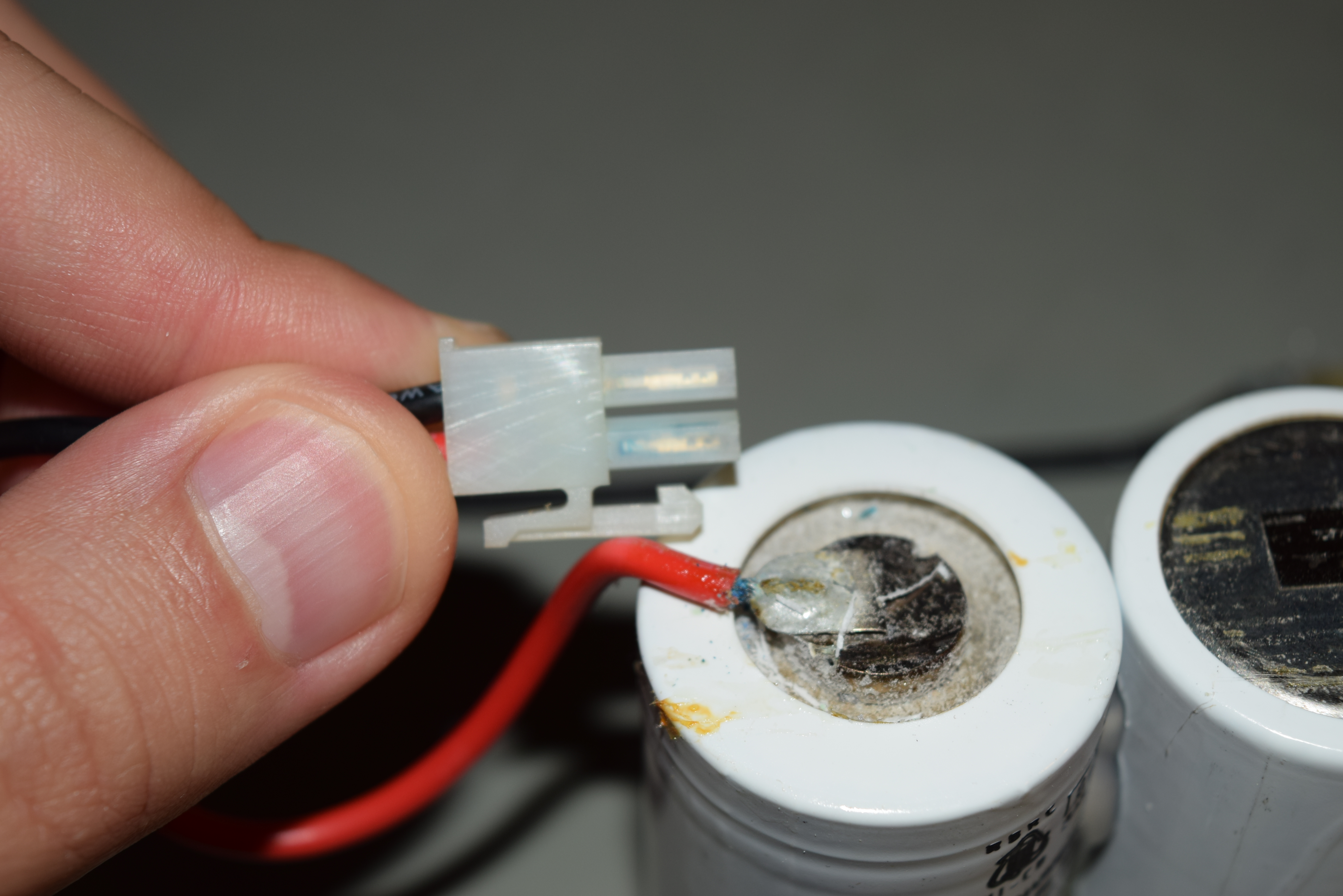
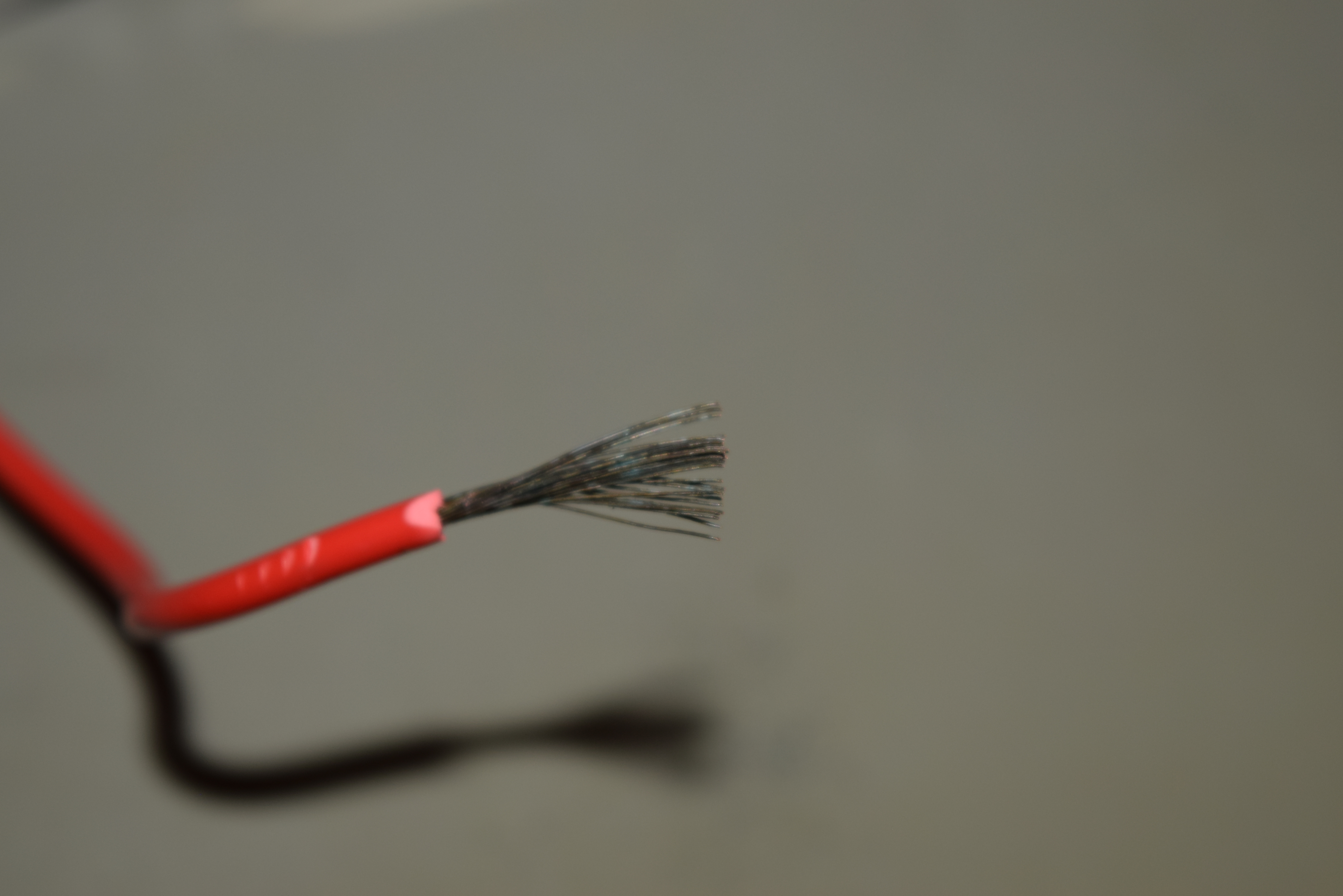
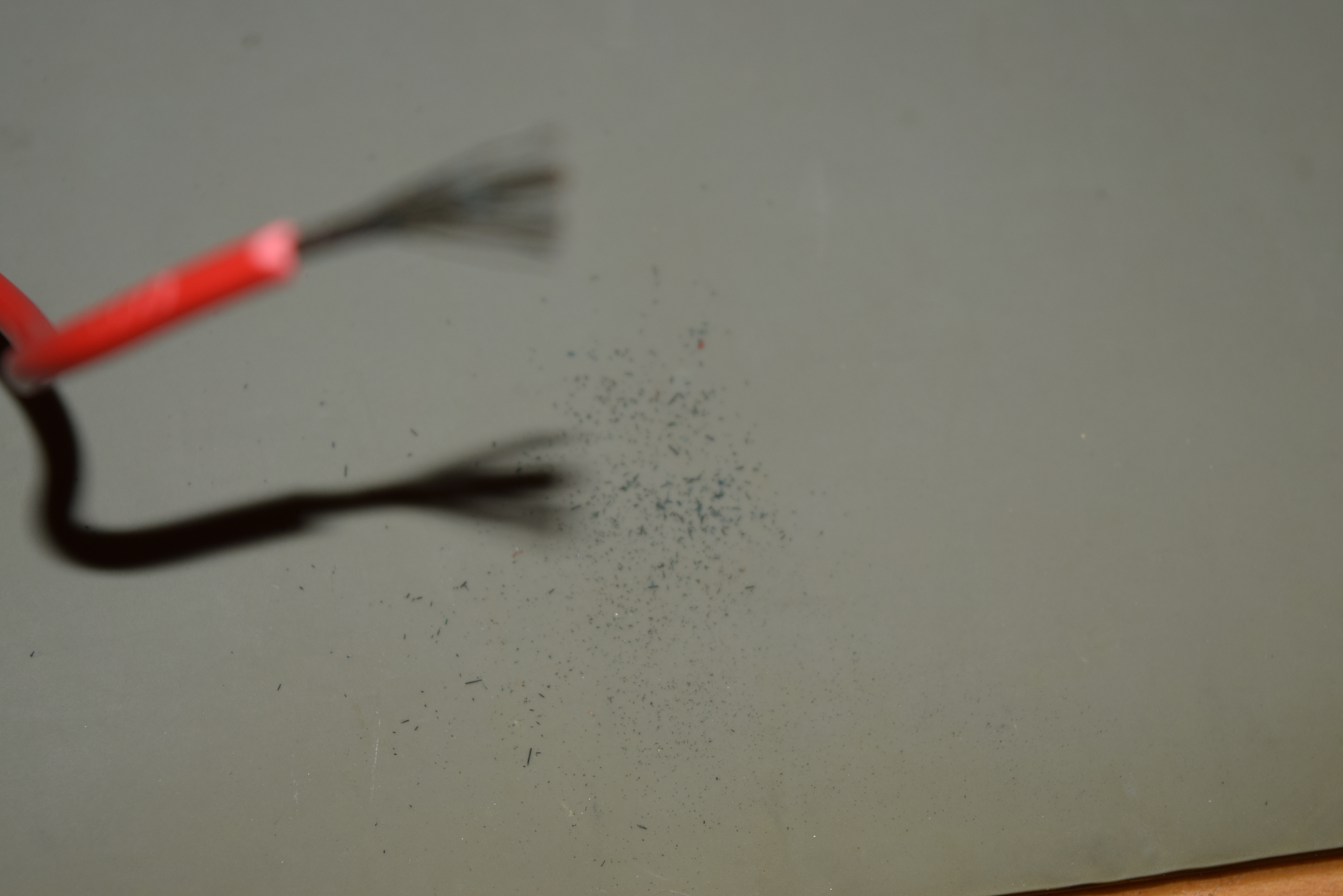
This pack has been sitting for so long that the cathode (+) wire is severely corroded (not all of them are like this). Even the connector turned green. I cut open the wires and gave it a tap, and a bunch of copper oxide bits falls off.

Now that I acquired the tools, parts and practice to make one from scratch (I used to need the old battery pack). It’s not cheap (given the tools, research effort, and most importantly, small quantity), but I can custom build them for you if you don’t want to deal with the hassle and steep learning curve.

The first pack is the most expensive, additional ones are much cheaper because of the reduced overhead. Lead time is around 1~2 weeks unless you pay extra for me to express order the ingredients.

You can call me at 949-682-8145 or just go to humgar.com.


Loading

xkcd 666 Timer IC: Maxim makes a MAX666

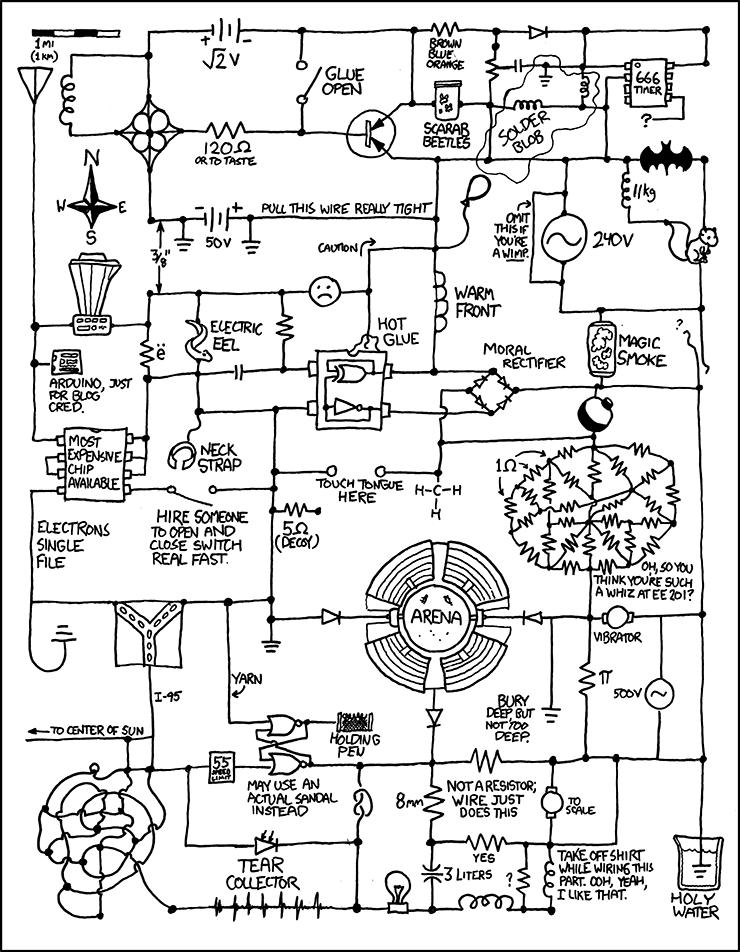
One of the most memorable things about xkcd’s (in)famous circuit diagram is the 666 timer (at the top right corner of the comic), a parody of the famous 555 timer:

Today I was analyzing the logic board for HP 3560A and noticed some batches uses a MAX666 chip and it immediately reminded me of this xkcd joke. Turns out Maxim Integrated makes a voltage regulator with a cool part number! I bet the engineers back in the days must have started with 666, giggling uncontrollably, and added 665 and 664 to see if it can get past the regulators or the censors (puns intended for both).


Loading

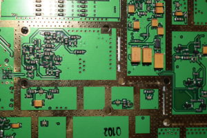
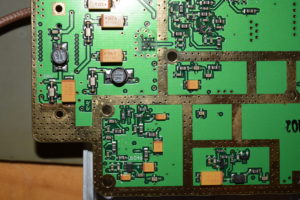
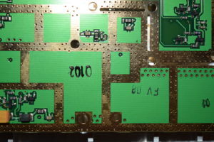
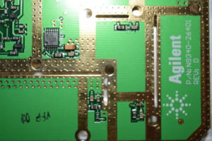
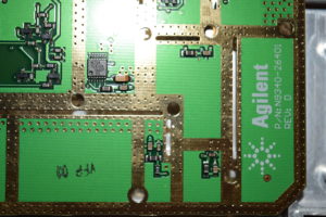
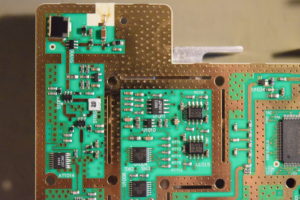
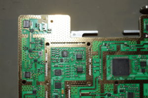
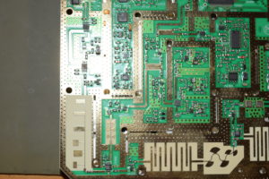
Agilent N9340B Handheld Spectrum Analyzer Repair and Teardown

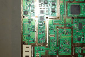
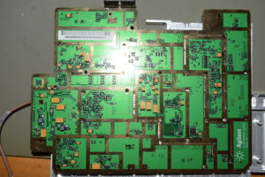
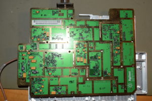
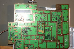
I received an Agilent N9340B 3Ghz Handheld Spectrum Analyzer with a note that it passes all self-tests but does not respond to input signals. I took the gamble that it’s the RF input connector got disconnected somehow.

I opened up the case and noticed that the 40Mhz cable was unplugged, so I was half-correct. I connected it and got a signal at the precise frequency, but the amplitude doesn’t look quite right. It’s around -20dB off. When I scanned it across the full 3GHz band, I noticed the amplitude roll-off when I scan below 800Mhz, and I got very little signal left when I get to somewhere near 10Mhz.

I tried running a user calibration with a 50Mhz CW source but it failed amplitude calibration. Apparently the unit is not fully working. No self-test errors though.

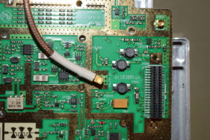
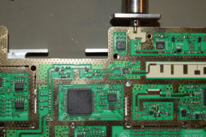
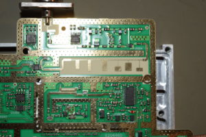
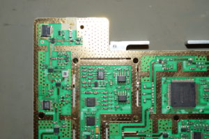
So I opened up the unit and the RF section. The front side of the board doesn’t have any visible signs or unusual smells, so I suspected the improper gains is caused by the input attenuator HMC307:

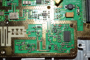
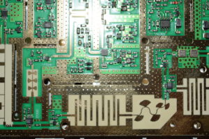
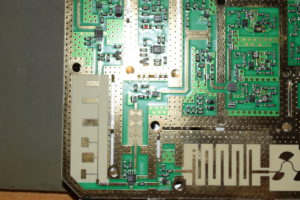
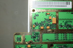
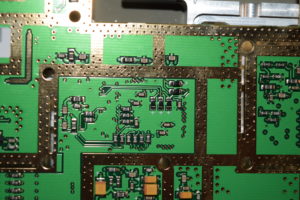
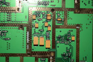
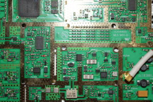
I was about to order the chip, but because of the lead time, I decided to just take a picture of everything and analyze it off-line:

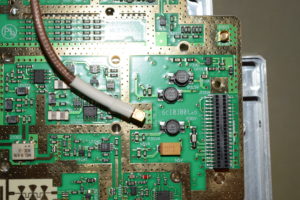
After removing the screws holding the N-type terminal so I can get to the back side of the board for taking pictures, I noticed the RF in connector just fell off the board with the pad:

That means the RF in is not touching the board! I resoldered the connection after I put the board and the connectors back to the RF module slab. Once I put unit back together, I turned it on again and everything works perfectly! The power level is flat and within 1dB of what my 8648C pumps out. I did the user amplitude calibration again, it passed, and everything was spot on!

Loading