Found a very good tutorial written by XP Power that concisely (short yet complete) covered all topics about power circuits that every circuit hobbyist should be aware of.
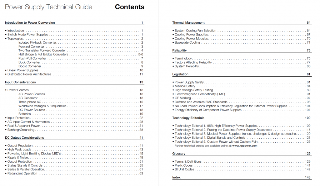
Here’s the book:
![]()
Found a very good tutorial written by XP Power that concisely (short yet complete) covered all topics about power circuits that every circuit hobbyist should be aware of.
Here’s the book:
![]()
BUZ80A (N-MOSFET) -> IRFBE30PBF
![]()
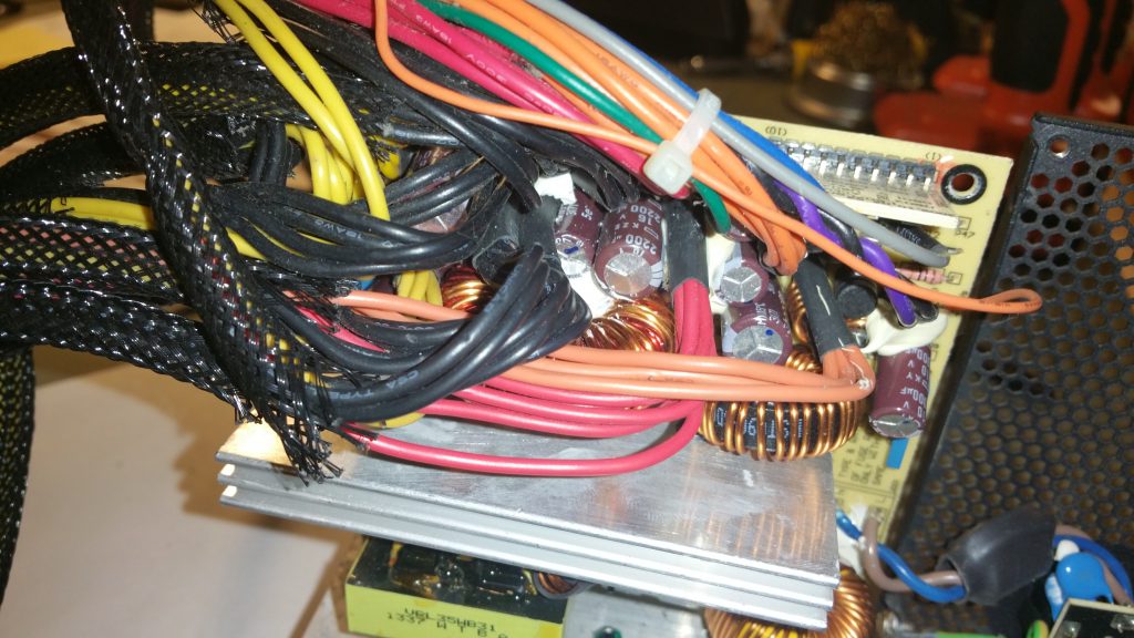
I opened up my ATX Power Supply as I had it for quite a few years but it has been stowed away and used intermittently until I use it a lot more in my office computer in recent years. I just don’t trust any power supplies Made in China, even from a reputable brand as a couple of decades of working with computers tells me that they are bound to break after a few years, and very often it is the capacitor that rotted and the rest are collateral damages. Lo and behold there is one:
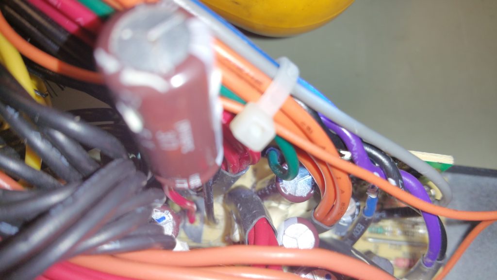
After I took the capacitor out, I noticed something odd: the polarity marker on the circuit board is the reverse of how the capacitor was installed! Holy smokes! I just want to verify if the PCB markings is right or the installer was right, so I installed wires to the capacitor to lift it up so I can connect the multimeter leads across it to measure the voltage polarity. This picture also shows the PCB’s capacitor orientation marking:
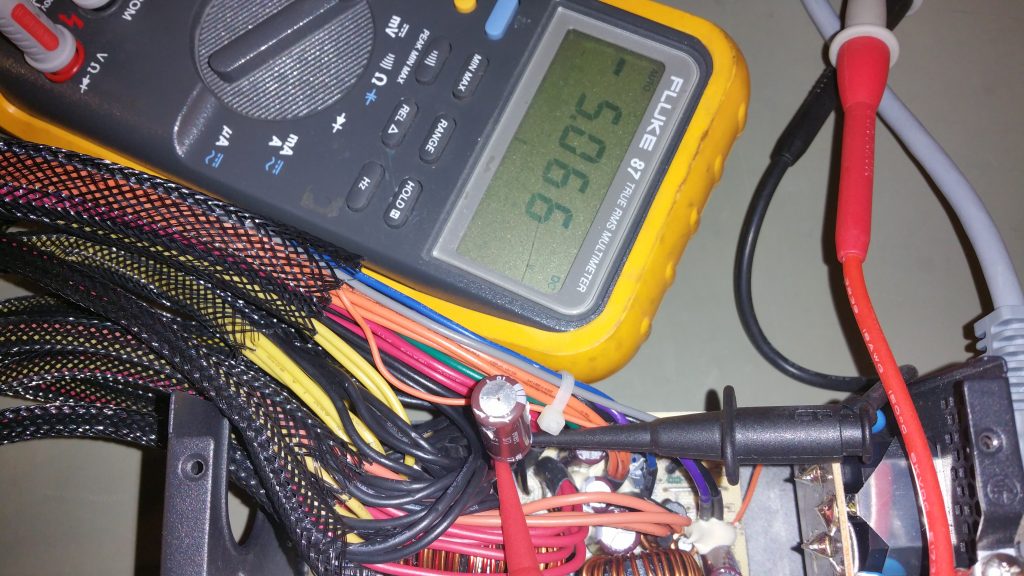
And the multimeter reads -5V following the original orientation of the capacitor before I took it out. This means the polarity was reversed!! No wonder the capacitor bulged. I was lucky that it didn’t blow up after a few years of use! Probably it was rated 16V yet only -5V was passed to it so the electrolytic capacitor rotted slowly.
To give XFX Force credit, they didn’t slap the power supply together with the cheapest white label components from the gutters. It uses proper Nichicon and Hitachi capacitor, so it might be the reason that reversed capacitor lasted so many years.
It’s the workmanship in China. If you go with a Red Chinese (Yellow-Soviets) brand, they might use junk components, but don’t think you are safe with foreign companies that has a solid process and design. The cheap labor in China who doesn’t give a crap can still manage to fuck it up. So trust nothing
ElectroBOOM!
![]()
The cutoff frequency of 10Hz on the datasheet is a typo. Better scopes at the time claims 90Hz. 10Hz is just too good to be true.

Found the specs from the service manual:
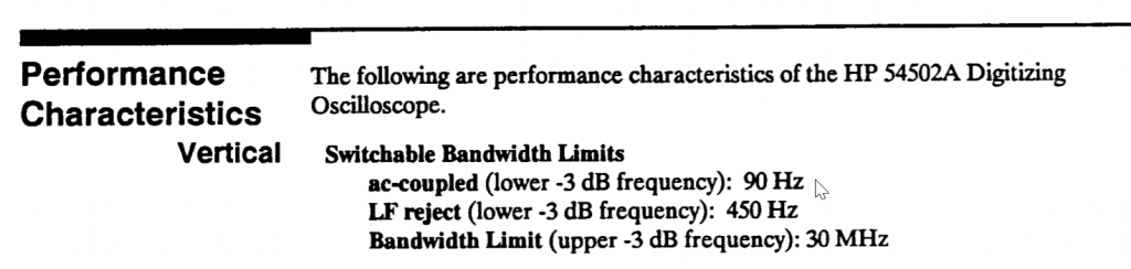
Don’t be fooled by the -3dB cutoff and ignore how wide the transition band can be (depends on the filter type and the order). Turns out this model has a very primitive filter that AC couple mode still messes square waves below 3kHz up despite the specs says the -3dB is at 90Hz. You better have a 30+ fold guard band for old scopes!
Remember square wave pulse train in time domain is basically a sinc pulse centered at every impulse of the impulse train in frequency domain superimposed. Unless you have a tiny duty cycle (which is not the case for uniform square waves, they are 50%), the left hand side of the sinc function at 1kHz fundamental still have sub-1kHz components that can be truncated by the AC coupling (high pass filter).
![]()
I tucked away my PC a little away from my workstation desk and the power switch is located at an inconvenient location. I tried to keep the wiring minimal so I’d rather not wire a dedicated ATX power switch onto my desk.
Unfortunately my motherboard does not support turn on by USB keyboard, and I’m not ready to upgrade because I am using it to test PCI data acquisition cards and it’s the fastest one that has 4 PCI slots and they are hard to find nowadays.
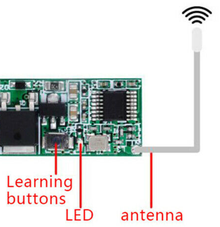
I found a $2.5 wireless module on eBay that claims to switch LED lamps which works on the standard 433Mhz channel and it replicates momentary switch pattern and can operate on 5V (My motherboard is new enough to have 5Vsb from onboard USB header).
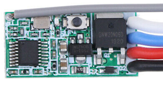
Initially I was tempted to get the built-in relay version, but I was worried about the current draw from 5Vsb and those are 12V relays., not to mention the footprint is much bigger (the one above is 22.5mmx 11mm x 8mm).
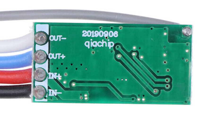
I thought I can figure out with some sort of BJT switch instead of using a relay that has a much bigger current draw requirement, but I realized it’s a pain in the ass because the output is ‘floating’ differential. The OUT- does not tie to the power ground (it’ll short out the unit when I tried to. That’s why I added quotes to ‘floating’ because it’s only relative to OUT+). I also measured OUT+ which is +5V with respect to power ground.
I tried to power a LED and it only works if current flows from OUT+ to OUT- so it’s really sinking current from source power to do that, and it’s unidirectional.
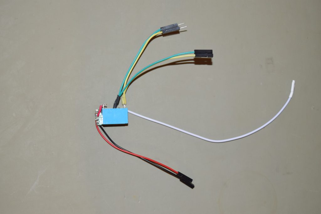
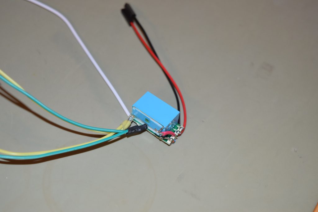
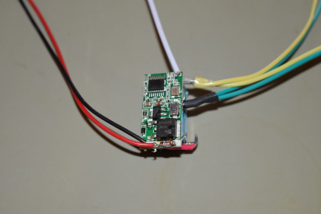
I’d just take a gamble and hook up with a 5V NO relay that I have around. Turned out it actuates with the 5Vsb from the USB header. I glued the relay to the back of the PCB and hook up a flyback/snubber diode (reverse biased) across the relay coil so the back EMF won’t fry my motherboard.
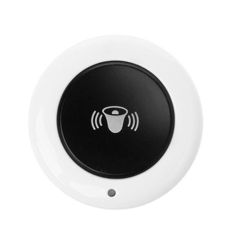
Seems like the transmitter-receiver pair is on momentary switch mode by default, so no addition configuration is needed other than pressing the learn button and immediately press the transmitter button to pair.
I wired a jumper extension cable (male – female) to the relay output from the middle as a by-pass since I’d like to keep the original power switch’s functionality (so it’s basically OR-ing between hardwired switch and the wireless remote 433Mhz switch)

Here’s an example of taking 5Vsb from USB header and tapping into the power switch jumper in Front-Panel jumper block:
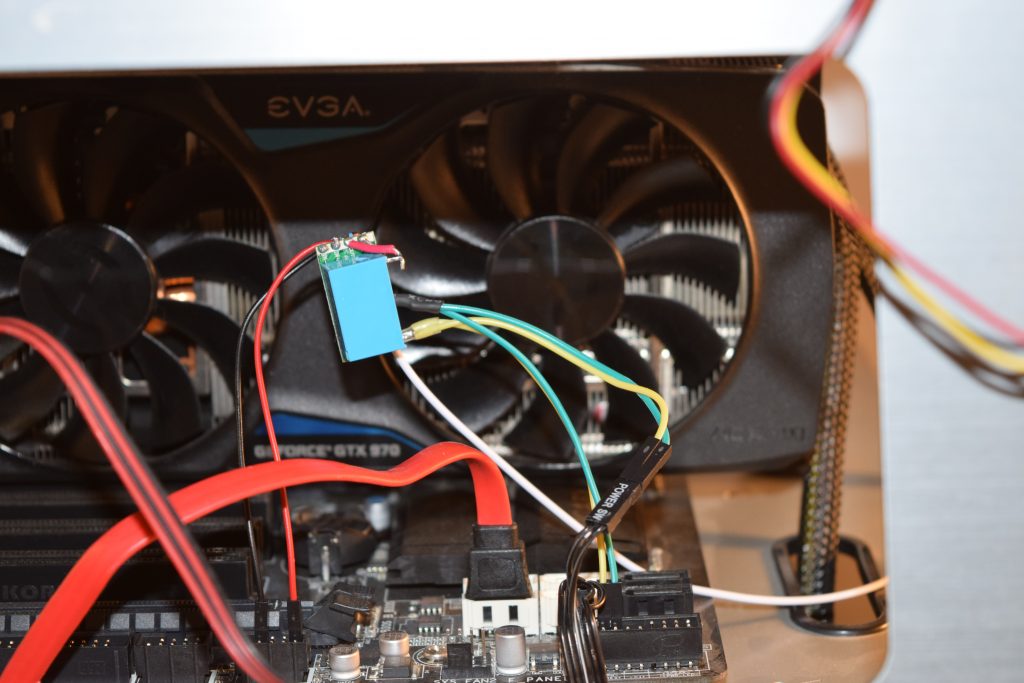
Note that the PWR SW- pin is connected to the ground. Since I’m using a relay, the relay output is floating so the polarity does not matter.
![]()