A few years ago I switched my stereo system (I’m using them as computer loudspeakers) to Class D because I was annoyed by the heat the professional (Class AB) amplifiers generate heating up the room (electricity bill aside).
I personally prefer the sound from Tripath amplifiers (started with LP-2020A and LP-2024A), which they called Class-T, but it’s really just Class-D with better PWM feedback mechanism. To drive bigger speakers with stronger bass, I bought a LP-2051 (50W x 2 RMS), which uses TP2150 (200W driver) + TC2001 (Audio Signal Processor) Tripath chips.
However, this amplifier has a very fatal flaw: it has a ridiculous loud turn-off pop! The system has speaker protection relays, so there’s no turn-on pop as expected as speakers are connected 3 seconds after switching on the power.
The turn-off pop bad enough that I was about to toss that in the trash as the amplifier fearing that it might damage by expensive and hard to get ADS vintage speakers. However Class-T chips are no longer produced and the TI Class-D chips for some reason just doesn’t have the clarity in the mid-range and high-frequency range I was looking for in Class-T amps, so I’ve decided to figure it out.
DO NOT TOSS YOUR Lepy LP-2051 Amp because of the loud turn-off pop!
There’s a simple way to fix it if you have a soldering gun, some wires AND a relay (normally open, 5V coil)!
Before I get to the solution, here’s a a few things I figured from observing the board which helped:
- The power line is 19V (the unit won’t turn on until it reaches 18V, so the acceptable range is 18V~19V)
- The unit draws around 1/3 of the turn-on power when the power switch is off. The switch is AFTER the power rail smoothing inductor and tank capacitor so they are charged.
- Turns out the speaker protection relays are hooked straight to the 19V plug input BEFORE the switch (two channel’s relay coils are chained in series, then to the collector of a NPN transistor acting as a switch)
- The 5V regulated (rightmost pin of 78M05 when viewed from top) is always powered even when the power switch is off.
[Failed] Attempt 1): was to disconnect the left/right speaker wires with 24V external relays switched by the front panel power switch (it’s passing 19V and 19V is enough to activate the relay). The reason is that the power droop faster than the relay disconnect when losing power.
[Mixed success] Attempt 2): I have a big power capacitor 0.12F as external power smoother (initially used to fix huge transient power draw for huge bass transients like drums), which slows down the power droop when the power is switched off enough there’s no power-off pop. However, this solution is very clumsy as reasonably sized 0.022F capacitors won’t slow the power line droop enough to avoid the turn-off pop. This observation gave me the idea that it’s the power-loss detection circuit not reacting fast enough for the system to do the proper ‘shutdown’ procedures (muting the output or disconnecting the speaker wires).
I initially looked into expediting disconnecting speaker protection relay when the power switch goes to off position, but realized it’s already done in the transistor switch logic (cascaded NPN stages) that controls the speaker protection relay as I trace the circuits.
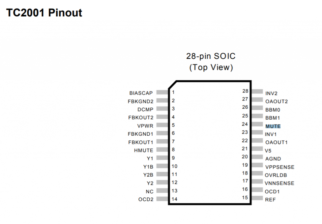
I started looking up the datasheet looking for built-in mechanism in the IC that mutes the amplifier as I switch the unit off (the unit is partially powered once the DC plug is in). Turns out there is: the mute pin is on TC2001’s pin 24 (MUTE):

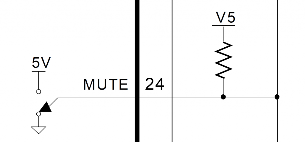
I tried flying pin 24 to the 5V regulated output (on 78M05) and it muted as expected. I didn’t really bother to check, but when I take out the jumper wire, it’s unmuted as expected (which contradicts with the datasheet description that floating is considered high/mute, so I assumed there’s other logic driving it low by default)
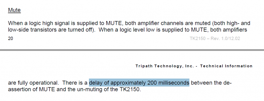
[Failed] Attempt 3): Use a NPN transistor like 2N9304 (and a potential divider to tap the 19V logic to 4.5V) to drive the mute pin (TC2001 pin 24) high (which means muted) when I power the unit off. The turn-off pop is still there because it turns out that there’s a 200ms delay for the mute pin:
So now the goal is to have mute activated (set to high) FIRST a little before the 19V power line gets disconnected. The timing order for turning on does not matter because the speakers aren’t going to be connected until after 2.5 seconds once it’s hooked up to the 19V source, it doesn’t matter what’s the logic transient logic level of the mute pin (it’s going to be NOT connected to the 5V when the SPDT power switch is ON steady).
Realizing that there the power switch acts the fastest, then the mute pin, with relay actuation being the slowest, and the power switch that came with the unit is a SPDT, I don’t even have to implement a timer to delay disconnecting the 19V line before it finishes muting. Here’s the winning solution:
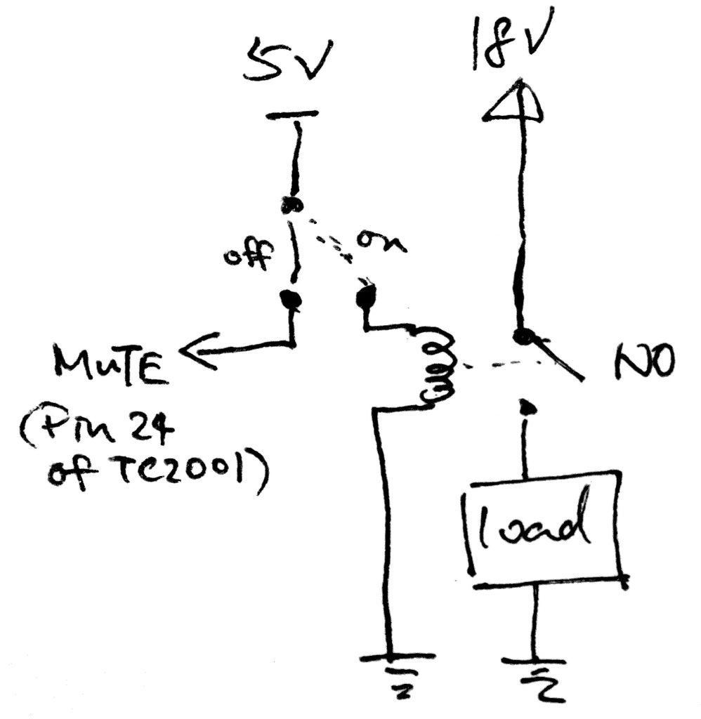
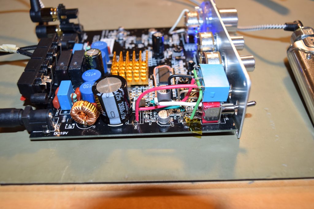
I happen to have a Fujitsu/Takashimaya JY5H-K5VDC reed relay which happens to be a NO (Normally Open switch) which happens to fit the design like a glove. Here’s a picture for the experimental (working) hook up that the turn-off pop is completely gone:
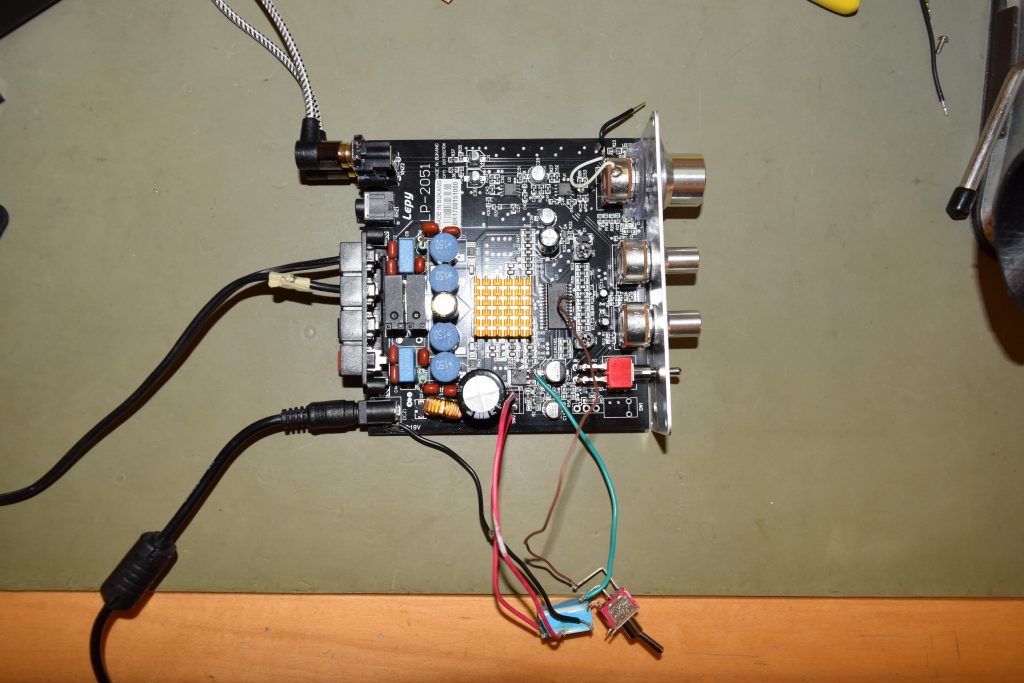
(FYI, the bottom node goes to 19V of the DC jack, the top node goes to the rest of the 19V circuit)
The 5V line is the green wire. Goes to the common/middle pin to be switched by the SPDT switch.
The mute pin (pin 24) is the brown wire. Goes to the furthers/longest pin of the switch
Ground is the black wire. Goes to any one side of the relay coil
The shortest pin of the switch goes to the other side of relay coil. I soldered it directly to the relay pin
Completed mod after cleanup:
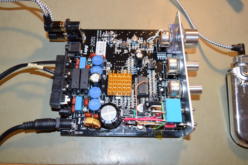
There’s a few cleanup that I did:
- I hot glued the relay on the two hard switches as they are not near any heat sources and mechanically stable
- I stole the ground (going to the coil) from the nearby C5’s ground pad (C5 is the moderately big 470uF SMD cap nearby).
- The old right-angled hard switch’s pins were lifted from the board by bending the pins straight.
- The utmost pin/pad (leftmost, closest to the power plug) for the switch is not connected anywhere else on the board. It was a dummy as the SPDT switch was only used as a SPST switch. Good for me so I can solder one of the 3 pins there for mechanical support (otherwise we’ll twist the front two dummy solder joints for mechanical stability when we toggle the lever repeatedly). I chose to bend the middle pin to solder it to the board because the other two are either too far out or too short.
- In summary, furthest SPDT switch pin goes to mute pin, the middle is the 5V regulated rail to be switched between the mute pin or the relay coil. The shortest SPDT switch pin goes to the coil. The rest are obvious
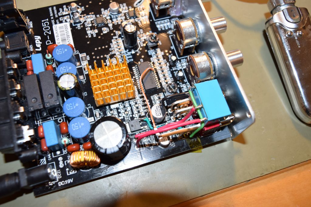
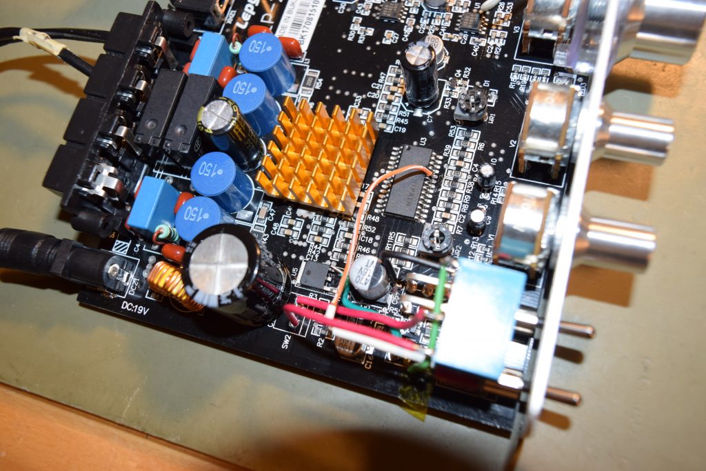
Here’s the finished mod with different angle shots for you to see the wiring:
Given the amp itself is cheap (but it’s really an excellent bang for the buck: clear sound, solid bass, class-D efficiency, small size and light weight), those who are not that electrically savvy might not be inclined to do that mod. If you are going to throw it away anyway, please send it to me (I’ll pay for postage).
It’s a very very simple mod that any beginner electronic hobbyists or an electronics student might be willing to do it for you with the instructions here for a small fee. Basically it’s just some wires and a relay and some good solder wick (or if you have a nice desoldering pump, it works fine too).
I typically don’t take petty service orders (under <$500), because of all the hassles shipping back and forth, opening it up, putting it back, and keeping records for the IRS, plus the liability risks. So please find a kiddo, hobbyist or tech to do it.
![]()
 , which
 ![\[V_0 = I_1 R_1 = I_2 R_2\]](https://wonghoi.humgar.com/blog/wp-content/ql-cache/quicklatex.com-8a663458bbae1bd300900f29783da92c_l3.png "Rendered by QuickLaTeX.com")
![\[I_1 = I_2 \frac{R_2}{R_1}\]](https://wonghoi.humgar.com/blog/wp-content/ql-cache/quicklatex.com-bf5abc1e2b679690553dbb791115aa9c_l3.png "Rendered by QuickLaTeX.com")
 . For example, in high school physics, we discuss why we have high voltage power lines for bulk energy transmission despite it’s more dangerous. The traditional explanation is
![\[P_{wire loss} = I^2 R_{wires}\]](https://wonghoi.humgar.com/blog/wp-content/ql-cache/quicklatex.com-5822e8c051bf4cd0f9674d96203c3ef8_l3.png "Rendered by QuickLaTeX.com")
![\[P = \frac{V^2}{R}\]](https://wonghoi.humgar.com/blog/wp-content/ql-cache/quicklatex.com-2ba1209480290362b3e71e57679a2963_l3.png "Rendered by QuickLaTeX.com")
 , NOT the load voltage
  .
.![\[P_{wire loss} = \frac{V_{wire}^2}{R_{wire}}\]](https://wonghoi.humgar.com/blog/wp-content/ql-cache/quicklatex.com-7010e2aa6673954160793f56b8425232_l3.png "Rendered by QuickLaTeX.com")
 , so you have to derive the assuming an arbitrary