Modern Motherboards with PCI support

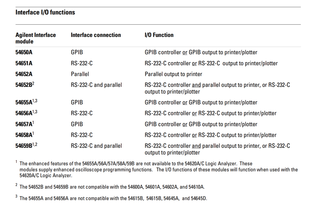
I work with a lot of expensive test equipment that relies on PCI bus, such as Acqiris digitizers and Agilent logic analyzers. They can work in computers as modern as Windows 10 and LGA1700 processors if you play your cards right (pun intended). There’s no reason to pay 10 times more to buy a PCIe card when a PCI card will do the job.

Contact me at Humgar LLC and I’ll help you figure it out if you plan to buy test instruments from me that requires PCI support, or pay for short consulting services to have me figure out the rough edges for you.

LGA1700 (12th~13th Generation Intel CPU)

  • Asus H610M-CT D4-CSM (1 PCI slot, microATX)
  • AAEON ATX-Q670A (3 PCI slots, Full ATX)
  • Advantech AIMB-788 (2 PCI slots, Full ATX)
  • Advantech AIMB 708 (4 PCI slots, Full ATX)

I also have other solutions such as using a short PCI bridge interface to drag your PCIe card out to take advantage of the unused extra space in the chassis, but these are subjected to testing and verification because every situation is different.

Nonetheless, hardware for accommodating PCI are chump change compared to the difference in costs buying a new card if you are talking about high end Ghz or 12~16-bit cards. Tell me your scenario and I’ll suggest whether you are better off buying a new PCIe card or adapting your computer/chassis to use PCI cards which are much bigger bang for the buck because of people’s irrational fear on compatibility.

Loading

Navigating between oscilloscope-land (Volts) and RF-land (dBm)

Have you ever been annonyed by the dBm and V units when you try to measure output from your benchtop signal generator (or arbitrary waveform generator, or ARB) with a spectrum analyzer, or measure a RF signal (sine) generator with an oscilloscope?

TLDR

For $50\Omega$ systems only. The fastest way is to work with squared voltages in linear scale with the provided ‘magic’ scaling factor (10 for amplitude and 20 for rms) and not mess with factorization in the log (dB) or anti-log ($10^{\frac{\mathrm{dB}}{10}}$) process:

P[\mathrm{mW}]=10V_{pp}^2=20V_{rms}^2
\mathrm{dBmW}=\mathrm{dB}\left(10V_{pp}^2\right)=\mathrm{dB}\left(20V_{rms}^2\right)

This happens a lot during calibration. An oscilloscope needs a 500Mhz signal at $600mV_{pp}$ to test if the front-end rolls off too early (i.e. have a lower bandwidth than advertised), yet my \$12k RF signal generator (20Ghz sweeper) only does dBm, and in coarse increments of 0.1dBm.

  • Decibel is supposed to be a dimensionless quantity, aka just a ratio.
  • The confusion came from people in each field abusing notations by skipping the reference quantity suffix after dB. e.g. RF people write dBW and dBmW (a dimensioned quantity with loaded assumptions of a $50\Omega$ scaling) as dB and dBm (which would naturally read as a dimensionless ratio)
  • When RF people talk about decibels, especially when they abuse notations by not mentioning the reference (basis) quantity, you can be pretty sure that they are talking about ratios between power quantites (dBW), not voltage quantities (such as dBV).
  • There’s no such thing as a $20log_{10}$ decibel unit. It’s always $10log_{10}$ dimensionless. The factor of 2 came from the square (power of 2) factoring out of logarithms as a multiple of 2 when ratios of power are expressed as ratios of voltages.
  • Always work in power ratios to avoid the confusion. dB is dimensionless but often the unspoken rule is that it’s a ratio of power quantities. Routines or formula like mag2db really mean magnitude_squared_in_dB because it’s doing $10log_{10}(A^2)$.
  • The other advantage of actually squaring the term first before taking the log is that you do not have to check the input for negative values as the squaring operation made it absolute value (square). If you are doing a logarithm, an extra multiplication (over an addition) is insignicant in terms of computational burden.
  • $V_{rms}$ maps directly to power quantities, scaled by the impedance (which is typically $50\Omega$). Everything else involves an extra crest factor (which is $\sqrt{2}$ for sinusoids)
Continue reading

Loading

TL866CS and TL866A recovery mode

I was playing around with my TL866 programmer trying to refresh the firmware and needed to get to the recovery mode. However, it seems like the recovery mode info on http://www.autoelectric.cn/en/note.html is incorrect for 2014 design (the one I have). I tried the 240\Omega as recommended with a decade box and it doesn’t work .

Usually my guess that if somebody is going to set a recovery mode in a micro-controller to be enabled with some hardware path to the power supply rail with a small resistor, it’s just saying that he wants you to pull the pin high.

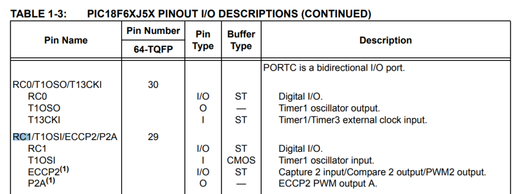
The said pin is a digital I/O line so I took it as a GPIO pin used for input (I might be wrong)

I measured the voltage of the said regulator with a decade box. Interesting that if I flip the resistance while the unit is on, it occasionally remembers the last state when I plug it in again! (EDIT: There is a Schmitt Trigger buffer in between. The buffer type says ST for RC1. Doh!)

Here are some of my measurements with a decade box:

Continue reading

Loading

54855A/54854A Oscilloscope won’t power on

Recently I got a 54855A oscilloscope sent back to me for service under the 1 year warranty I underwrote for most of the unit I’ve sold direct. The unit would not turn on at all after sitting for a long time.

I looked up the forum and it turns out other people had this problem with a certain generation of Infiniiums and sometimes changing power supply or motherboard would disturb the setup a little bit and the unit might power on again. When I tried to do that, the unit does boot a quite few times but the problem randomly came back again. This is frustrating as it’s a heisenbug. I almost thought I was done when the unit worked consistently for a week then it comes back. It just looked like something component was acting borderline and disturbing the setup and got it to click.

In the past I had 54830s that’s ‘fixed’ by changing either one of the motherboard or power supply, but turns out that those were flukes, but I didn’t get lucky with 54850s this time.

The customer gave me time to troubleshoot deeper instead of just getting something to work as a fluke by just blindly changing modules which might break down again at a random time if it’s a gravitating aging problem (i.e. if you figured out a problem, it tends to be a wave of manufactured gears that’ll trip on the the same issue as they age). So I spent a whole month troubleshooting through reverse engineering the circuit and nailed down the cause and the fix.

There’s a lot of mixed info going on in the forum with different modes of failure, but those might not be the real cause, as replacing components disturbs a set up that wasn’t supposed to be in that state in the first place and the unit is prone to get trapped into a bad state when the unit ages. The real fix is to plug the path to the bad state in the first place instead of rocking the boat hoping the new combination doesn’t trigger the bad state.

Continue reading

Loading

Agilent LCR meters: typing profile names painlessly without using instrument keypad

For newer LCR meters where you can label your measurement setups before saving, using the context menu to enter the names is a painful task, and it shortens the life of the keypads. There’s a quicker way to enter it: send GPIB commands (use Agilent I/O) to it. The command is:

DISPLAY:Line "Profile Name 1"

which you can replace the “Profile Name 1” with anything. Keep the double quotes so the parser won’t be confused by special characters such as minus/dash (-) signs.

If the unit supports LXI (i.e. network interface) such as E4980A, so you can send the GPIB commands through network using Agilent I/O Suite.

Loading