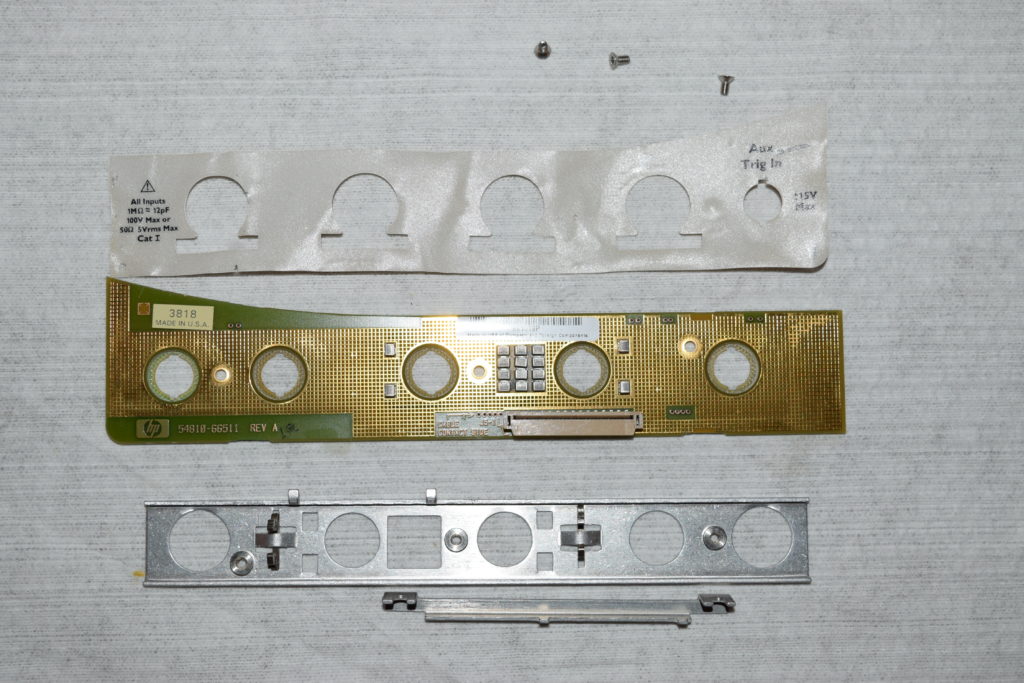
Teardown of Infiniium probe interface card 54810-66511

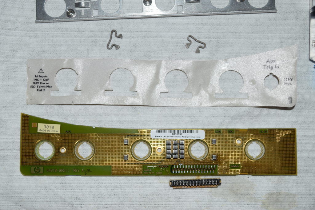
I have a bad probe interface card from a 4 channel unit. Since the label at the front is nearly impossible the transfer, and the screws was put on before the label covers it, plus the FFC connector is impossibly tight even for hot air to get there without much damage, it’s near impossible to save it with a 2 channel card.

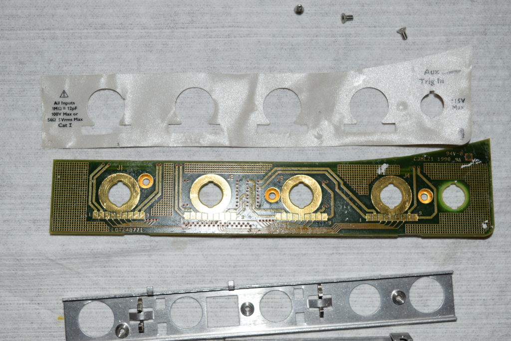
Out of curiosity, I removed the label sheet to see what’s inside it:

The PCB is the same for 2 channels or 4 channels. The 2 channel version simply have channel 3 and the aux trigger hole covered (channel 4 is the external trigger port in a 2 channel model). So technically, you can cut out the excess label and cover up the “Ext Trig” text, but it won’t look professional. If it’s your personal unit, then feel free to go with the hack.

Loading

Infiniium front panel keypad 54810-66504 (2 channels vs 4 channels)

54810 series (first generation) Infiniium uses the same PCB for 2 channels and 4 channel models. They slap on a different rubber keypad sheet and the button labels depending on whether it’s a 2 channel or 4 channel model.

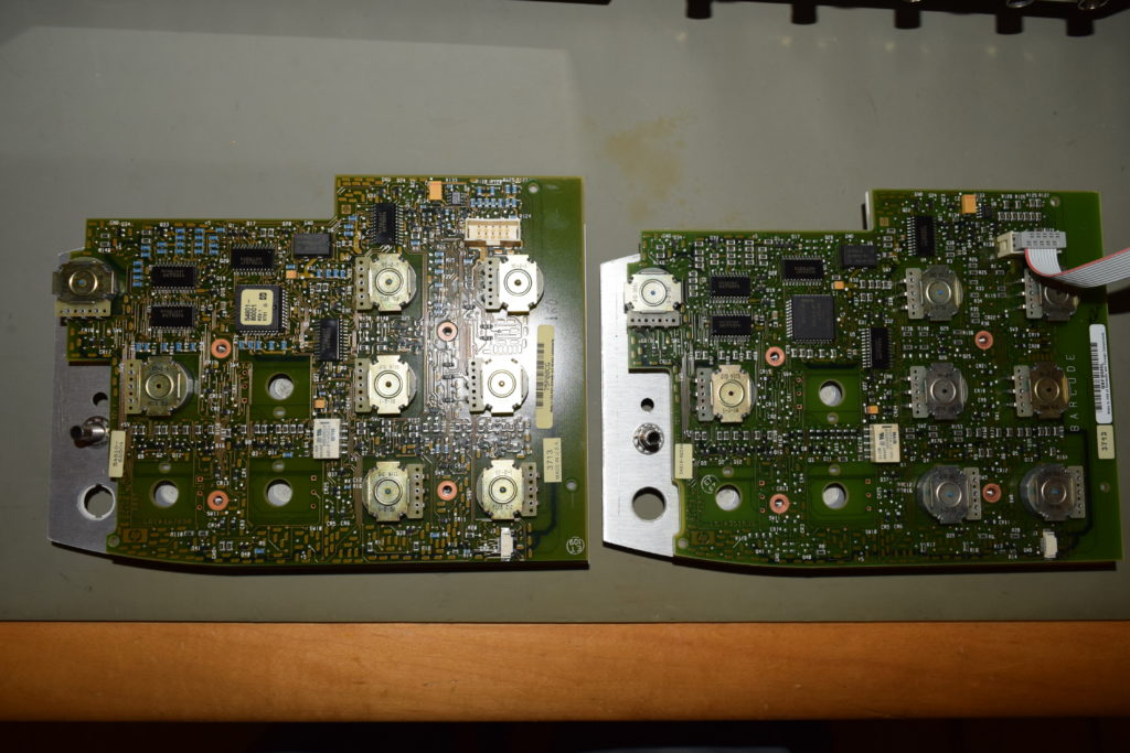
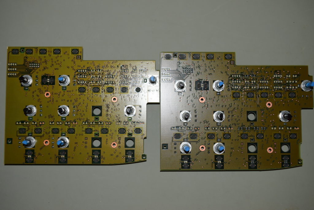
I received a 4-channel front panel keypad module that was ruined by ripped pads around the relay while trying to replace it. Instead of trying to fix it, I transferred the rotary encoders to a 2 channel PCB which are in abundance, and I noticed this:

It seems like HP/Agilent at some point tried to save a few pennies by skipping the SMD grains (resistors, capacitors, inductors, transistors, diodes) surrounding Channel 3 and 4 for the newer board on the right.

So if you are looking to repair a 4 channel front panel keypad with 2 channel PCB, you should preferentially select ones from the older lot which has all the parts for 4 channels populated except the rotary encoders. If not, time to get a pair of SMD hot tweezers and transfer the grains one by one.

Loading