Option 005 “Vertical Output” port of 54600 series oscilloscopes (54616B, 54616C, etc) A secret backdoor feature that new oscilloscopes lack

Over the last year, I got a couple of requests for 54616B that specifically ask for a “vertical output” port at the back. I have never seen an oscilloscope that came with such a port, including a few hundred of first generation first generation 54600s I acquired from many different sources.

I got curious and looked it up. Turns out it’s a secondary feature of a relatively obscure option (only mentioned in the manuals, but I have never seen one) called Option 005, which lets you analyze (like count lines) and trigger over common TV signals, like PAL/NTSC/SECAM, which is way obsolete today. It also seems that none of the customers asking specifically for the “vertical output” port at the back know that it is a super rare option that is normally not included, so they must be using it for something else other than analog TV signal analysis.

A closer look at the user guide shows that “vertical output” port duplicates the signal source (e.g. channel 1) that the scope is triggering on, limited to what is seen by the oscilloscope, to the said “vertical output” port, a secondary feature to let you chain your signal to instruments like spectrum analyzers for further analysis.

I tried the feature myself by chaining the output to another oscilloscope. Even if the waveform is off-screen for the current vertical volts/div, the vertical output port waveform did not clip. I also played around with input impedance settings 1MΩ and 50Ω for a 50Mhz square wave. Based on what gets the square wave badly distorted, I can confirm that the vertical output signal is the analog signal after attenuator (the amplitude changes only with Volts/div that causes relay clicks) but before ADC, assuming a 50Ω load.

Wait! An oscilloscope that duplicates the input analog signals after being processed by the front end (post-attenuator, pre-ADC) to an external output port?! I don’t have to mess with the original signal path by splitting the signal (passively) or make an amplifier to duplicate the signal? Wow! How come it’s not standard (or at least a purchasable option) in modern oscilloscopes? I’d like to see what’s going on with the analog waveform before the scope processes it! Not only it’s very educational, it allows other instruments to get an accurate insight of what the oscilloscope is seeing. Neat!

Installing the Option 005 is not difficult if you happen to have an unobtainium Option 005 case with labels, and the entire kit with all the necessary interconnect. However, it’s like an unicorn and I’ve never seen one. Drilling professional looking holes for it is a nightmare as we don’t have the dimensions. The hardware is also insanely hard to get as it was made for a specialized crowd for the time and practically nobody cared about analog TV signals nowadays. Even if I can get that, they are most often missing the interconnects. The ribbon cable is missing for nearly all of them, and if you get a standard ribbon cable, you’ll realize the plastic retainer gets into the way of a screw on the main acquisition board so the Option 005 card won’t slide in unless you trim some of the plastic off. PITA!

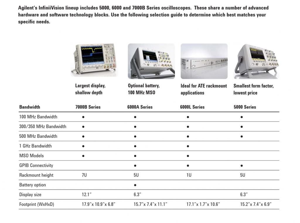
Nowadays I am already spoiled by high end gears like MSO6054A and 13Ghz Infiniiums (like DSO81304A), but none of them has a convenient analog, post-attenuator output like a first generation 54600 with an Option 005. Given the hardware is scarce, I’ll save it for the top of the line first generation 54600 series, namely 54616B and 54616C.

For those who have this special need (need to tap into the pre-ADC signals up to 500Mhz), I can custom build these Option 005 units for you, depending on parts availability. Call me at 949-682-8145 or reach me at my business website www.humgar.com.

 750 total views

Agilent (formerly HP, now Keysight) vs Tektronix

I am much more inclined towards Agilent than Tektronix because

  • There’s nothing a Tek scope can do that an Agilent can’t
  • Agilent’s user interface is very intuitive that it requires little to no trial-and-error or RTFM.
  • Agilent’s people are often very generous about helping customers out even if support is discontinued. Tek gets rid of all service information and software after discontinuation by policy.
  • Agilent’s gears are very thoughtfully designed and is a pleasure to service, for the ones that I have opened up so far. Tek designed their unit to live barely enough through their support lifecycle, hoping they won’t have to service it.
  • Agilent’s old gears lives much longer. Just look at (even better, open up) Agilent 54600 series and the damn TDS 300~800 series and you’ll see what a nightmare Tek is.
  • Tek’s autoscale algorithm is a piece of garbage!
    Even with TDS6000B/C series that cost tens of thousand of dollars at the time of writing still couldn’t figure out the top Ghz signals and give you a long Time/Div that completely aliases the signal and therefore confuse the heck out of their users. Not to mention Tek’s autoscale is sometimes too dumb to figure out which one channel you are on so that you have to move to (highlight/focus on) the right channel. Never had to deal with this kind of nonsense while using an Agilent scope.
  • Agilent’s gears also have much fewer hard/painful to fix aging problem than Tek.
  • When Tek scope fails, it’s often followed by a bunch of other unrelated aging problems. The capacitors are not designed to stand the heat for 10 years of usage.

EDIT: It’s not just me bitching about how unresponsive the controls (especially the dials) are in their user interface. Dave Jones did a video review of MDO4000 and a bunch of people share the same frustration in the comments section. I thought they improved after TDS1002B (I stopped following their newer scopes), but I was wrong. Still the same poorly thought-out and laggy UI.

There is Lecroy, but there are much fewer old gears in circulation and I don’t like their user interface much either, but at least the dials won’t take more than half a second to respond like Tek. I once asked Lecroy if they can generously share the schematic for an old unit like Agilent and they sent me one. At least they are not being a d**k about it like Tek.

I have both used Agilent and Tek scopes for sale, but my own bench is all Agilent whenever there’s a choice. Tek is OK if you plan out a difficult measurement setup (for documentation or manufacturing), but miserable if you are poking around to troubleshoot (that’s what I use the gears for). I sell Tek just to cater those who have been brainwashed because Tek got the first-mover advantage back in the days.

Of course my bias is based on their Tek’s gears in the digital age. I heard that they were very good at the analog scope times, so that might be the reason why Tek still have a strong following. HP/Agilent/Keysight pretty much nailed the digital techniques. The part I liked about Agilent is that they are generous about making users of their products happy in general, regardless of whether you recently paid them or not. For deeply discontinued products (like 3+ generations ago), they are happy to pass whatever information they have left to help DIY-ers or non-chartered 3rd parties that are willing to service them (like this one, which people are asking for recovery discs for their 1680 series analyzer and the staff went all the way to dig up their private stash!) so the company can focus on the newer products.

Support culture aside, Tek’s used gears are so problematic (I learned it first-hand, the hard way) that I’m now hesitant about buying them as investments. It looked like an opportunity because Tek stuff often breaks the same way, so I can buy them cheap, fix them, and resell. But the reality is that the labor is simply not worth it. Now I’m just selling whatever Tek leftovers I have strengthened in the past.

You might think Agilent is sabotaging their own market by taking care of users of their old gears. It isn’t. Whoever that has the budget to buy new will do so. Wobblers between buying new/old gears are not worth agonizing over. The ones who are familiar with the older gears will grow fond of the brand and the user interface/environment they are familiar with and will push their employers to buy Agilent when they get a chance to buy it new. I used to have a customer that I convinced them to get a used Agilent one instead of used Tek, and they ended up loving it so much that they bought a new one from Agilent for their second scope. What goes around, comes around.

I realized throughout the years is that whatever hobbyists do with the old gears and can only help the brand image and build a stronger user base. It’s the user base (engineer’s familiarly) that makes or breaks the deal on new gear purchase. I don’t think big companies that pays good money to buy new will switch to all Tek from Agilent all of a sudden when all engineers are comfortable with Agilent’s stuff, and vice versa.

 1,334 total views

Oscilloscope Probing – Bob Pease Show

Once in a while customers ask me about what probes do they need to go with their high bandwidth oscilloscopes.

Agilent already has application notes about how to probe properly at high frequencies to ensure what you see on the scope represents the reality faithfully, but they are a little dry. Bob Pease Show at National Semiconductor (now acquired by Texas Instruments) talked about it and it’s great infotainment due to Bob Pease’s character:

This show has significant product placement by Tektronix, but the information there applies equally (and fungibly) to all major name brands such as Agilent/HP/Keysight and Lecroy. They all live up to the specs advertised.

What I’ve learned from the video

  • No-name brand probes might not live up to the claimed specs. I wouldn’t trust a Chinese probe beyond 100Mhz (or even 60Mhz).
  • Shorten the ground leads as much as possible, especially high frequencies. Wires are inductors/antennas.
  • Do not use the poor-man’s differential probes (aka subtracting the channels on the scopes): the channels aren’t matched perfectly, the probes aren’t matched perfectly either.
  • Design for testing: plan your PCB so you can probe easily.
  • For digital designs, high bandwidth scope users care more about (time-domain) step response: rise-time, ringing, settling, than it’s frequency domain (I don’t have a fast pulse generator, this is why I test it with a RF generator to check the specs)
  • Active probes have less loading and attenuation. You can use passive probes if you have a large enough signal to burn.
  • Probe capacitance (loading) kills a fast circuit (by damping it down)
  • Don’t be happy because you see nice waveforms and nothing bad happens with a low bandwidth scope+probe: you are just failing the capture transients.

 778 total views

Quick setup guide for Agilent E2050A GPIB Gateway

For the convenience of my customers, I compiled a quickie setup guide so they don’t have the RTFM.

E2050A does not have DHCP. Most likely your network doesn’t have a ancient BOOTP server, so it means you are better off letting E2050A have a static IP address.

The big idea is that you’ll first need to talk to the E2050A, and the only way it can happen is that the computer talking to it has to be on the same subnet (and the corresponding IP address range). Doesn’t matter how you achieve it as long as you keep this in mind. Once you gained access to the router (telnet config screen), you can change the network setting of the E2050A to match whatever network you want to put it on later.

If you don’t know the E2050A’s network configuration, reset it to the default so you have a deterministic starting point and follow the instructions below:

  1. Reset the instrument to factory state by holding down CONFIG PRESET switch while applying power, because you want to know the IP address for sure so you can get into the instrument.
  2. The default static IP address is 192.0.0.192, under subnet mask 255.255.255.0
  3. Most likely your internal network is not 192.0.0.XXX, so you might want to use a computer with a network card (NIC) to talk to the device directly* (point-to-point) first so you can gain entry to the E2050A and change its network configuration.
  4. The NIC on the computer talking to the E2050A must be set to an IP address in the same subnet. This means only the last (rightmost) group of the NIC’s static IP address can be different. An example for the computer’s NIC static IP setting: 192.0.0.190 with subnet 255.255.255.0.
  5. Now you can talk to the E2050A directly by addressing 192.0.0.190. If it’s a dedicated computer for an automation set and you don’t want it to talk to the rest of the network, you are done.

I made up 192.0.0.190. Anything from 192.0.0.1 to 192.0.0.254 works. Thou shalt not use 192.0.0.0 (for it is the network identifier) or 192.0.0.255 (for it is the network broadcast address) or 192.0.0.192 (as it conflicts with the E2050A’s IP).

Most likely you will want to put the E2050A on your home/business network for convenience, unless you want to eliminate network security issues. Then you’ll need to follow a few more steps:

  1. Telnet to the E2050A at 192.0.0.192 to change its static IP address and subnet to fit your network. After saving and rebooting, you must address it with the new IP address you assigned (obviously!).
  2. Note that the default (SICL) interface name on the E2050A is “hpib”, which is different from E5810A’s default “gpib0”. Either change it on the E2050A (it’s called “hpib-name”) or enter the “hpib” for interface name on Agilent’s I/O suite.
  3. You can leave the rest of the settings alone in Agilent I/O suite if you want to simply talk (in its raw, instrument-specific GPIB commands) to the unit without using VISA or SICL layers (standardized syntax).

E2050A has the same software communication interface as E5810A, so you can just select E5810A as the remote interface for the E2050A and remember to enter the correct interface name as discussed above.

Note that E2050A does not work properly (won’t detect) on the redesigned Keysight-branded I/O Suite until version 2019. Please either use version 2019 and after OR the older Agilent branded I/O Suite.

I have E2050A as well as E5810A for sale. Please contact me from my business website (www.humgar.com) or my phone 949-682-8145.


* Unless you are using a very ancient computer, the NIC can auto-negotiate direct connection that you can simply use any regular old straight RJ-45 cable. If you have a really old computer, you’ll need a cross-over cable to do point-to-point ethernet.

 945 total views

GPIB to Ethernet Gateway (Agilent E2050A or E5810A, NI, Tek, ICS) Don't bother with USB-GPIB adapters. Ethernet-GPIB gateways are cheaper and better.

GPIB gateway is a device that allows you to remotely control / talk-to test instruments (as well as ancient printers/plotters, etc) that uses the most popular protocol. It’s so popular and timeless that even new test instrument finds a way to support it. This protocol just wouldn’t die.

The major downside of USB-GPIB interfaces (cheaper) is that it requires driver support, which is OS dependent. Keysight can choose to drop support at anytime. You can always fire up a virtual machine to use old software talking to a hardware using TCP/IP, but not reliably with USB (sometimes you get glitches and timing issues with virtual machines especially when it streams live data even at kHz range).

It’s usually a good idea to stick with GPIB if you have an automation setup that involves at least ONE piece of test instrument on GPIB. A ethernet port (LXI) on a modern test gear is fine, but you don’t really want to complicate your code managing network connectivity checks for each IP-based instrument and make sure they work together. With GPIB, you can chain 14 instruments with one gateway so you don’t have to worry about network problems if you can connect to any one of the device on the chain.

Here’s a nice GPIB tutorial document if you’d like to get into the nitty-gritty:
http://www.essproducts.com/wp-content/uploads/2015/06/ab48_11.pdf


E2050A is my favorite GPIB gateway due to its compact size. It’s good enough for most purposes, since I don’t really have any instruments that need or support the extra speed from 488.2. The biggest annoyance is that E2050A does not have DHCP, but uses an an ancient BOOTP instead. This means for modern networks, you might as well give it a static IP.

E5810A is the newer revision of E2050A, with the same internal interfaces. That means all software, including Agilent I/O Suite, fully supports E2050A as a E5810A. E5810A comes with a few minor improvements

  • it adds a web interface (not very useful other than upgrading firmware)
  • supports 488.2, which means 9x faster GPIB communication if the instrument supports it
  • DHCP: automatically acquiring IP address

Unfortunately, E5810A is a bigger unit, partly because the power supply is built-in, and it comes with a LCD screen. Nonetheless, I opened up a E5810A and the inside has a lot of empty spaces.

Telnet is supported for both E5810A and E2050A. For E2050A, telnet is the only way you can get inside the unit and change the configuration such as IP address and interface name. Telnet is pretty easy to use, just get the free, open-source Putty if your Windows does not come with command line telnet anymore.


There’s a E5810B, but in my opinion, it’s pointless because all it adds is a USB-over-IP interface and a front switch. This is something most ASUS routers (especially Merlin firmware) has it out of the box or there are some cheap old USB-over-IP modules (<$50) for it.  Basically if you are considering a E2050/E5810, your eyes are on the GPIB instrument base, not the USB instruments that you can put on the network with low cost USB-over-IP. It’s just fluff for Agilent/Keysight to discontinue support for the earlier models to price differentiate from the units circulating in the used market.


I’ve tried other gateways such as NI and Tektronix. There are not many NI gateways floating around and I’ve only encountered even fewer Tek gateways. Unless you have poorly written software that hard-codes to NI or Tek stack, I wouldn’t even bother installing NI/Tek GPIB stack as it can confuse some poorly designed software if the 3 stacks are not configured properly to work together peacefully. Just stick with the GPIB stack from the brand that you can easily get used units for cheap.

Be very careful about NI GPIB-ENET: it does not support anything after Windows XP at all, and there’s no way NI will bother to go back and fix it. For this I wouldn’t even want to touch any GPIB gateways done by NI since they are not as thoughtful about backward compatibility compared to HP/Agilent/Keysight.

ICS was popular a while ago making cheap GPIB controllers/converters. However, they don’t work with Agilent’s I/O suite or NI/Tek stack directly, so you are stuck with using it like a serial port. Given that the price of a used HP/Agilent’s GPIB gateway is cheaper than a new ICS gizmo, there’s no point getting ICS stuff anymore.


I have E2050A as well as E5810A for sale. Please contact me from my business website (www.humgar.com) or my phone 949-682-8145.

 1,193 total views

The mess converting decibels to voltages in test instruments (dBm, dBW, W, dbV, V)

Complex conversions between decibels and physical quantity has always been a rich source of confusion. The reason is that dB(something) is actually a loaded word with hidden assumptions:

  • dB always works on base-10
  • dB is always a relative (dimensionless) POWER quantity.
    The POWER quantity can be expressed in terms of non-power quantities (like voltages).
  • the scaling factor is always 10 for power.
    Adding one zero (multiply by 10) to the power ratio means +10dB.
  • dB(something) is always with respect to a quantity (the something), and the reference quantity is often not written in full. Since there is an implicit reference, db(something) can be mapped to absolute quantities.

If you are a diverse multi-disciplinary techie like me (math, electronics, programming, computers), it’d frustrate the hell out of you when you talk to people who has been working exclusively on a narrow field for at least a decade and they have a table of commonly used numbers in their memorized: they act like you are supposed to know how to get the numbers in the dB-variant that they use, than explaining to you what the field-specific assumptions are (likely because they forgot about it).

I hope this post will clear up the confusion by working out an example in test instrumentation, most commonly in RF as well, converting dBm to Volts.


Before I start, I’ll clarify the most common form of beginner confusion in EE and physics: converting between dB and voltages:

\mathrm{dB} = 20\log_{10}(V) = 10\log_{10}(V^2)

This looks like a definition of decibel, except the scaling factor is 20 magically for Volts. It is correct because we always work in power and power can be expressed as voltage-squared (resistances in the divisor cancel out if they are the same). Most people take it as an equivalent definition of decibels, and throw away these important assumptions behind it:

  • the reference is 1V,
  • and the resistance* (common to the voltage of interest and the reference voltage) gets cancelled

and run into troubles when they venture into those dB-variants like dBm. Technically the above should be written as dBV, but I have seen very few people use the clearer term.

The decibel formula for voltage came from

\mathrm{dBV} = 10\log_{10}(\frac{P}{P_{ref}})

where P = \frac{V^2}{R} and P_{ref} = \frac{1^2}{R}, you get

\mathrm{dBV} = 10\log_{10}(\frac{V^2/R}{1^2/R})

The R get cancelled out and you get

\mathrm{dBV} = 10\log_{10}(V^2)

People moved the squaring out and lumped (multiplied) it with the scaling factor 10:

\mathrm{dBV} = 20\log_{10}(V)

So the whole reason why it is 20 instead of 10 is simply because P\propto V^2, and \log(V^2) \equiv 2\log(V).


Now back to the business converting dBm to dBV or Volts.

First of all dBm is dB(mW), NOT dB(mV). The RF/telecom people are just too lazy to write out the most important part: the physical quantity expressly, because nearly all the time, it’s the power that matters to them.

However, I often need to connect a RF generator to a high bandwidth oscilloscope, so the very self-centered RF/telecom nomenclature start to become problematic when people of different fields need to talk to each other. Oscilloscope see everything in volts. RF sees everything in power, often in dB.

Then we get to the (mW) part, which means the reference quantity in the definition is 1mW, which is a physical quantity with dimensions. Then how are we going to convert it to Volts? You cannot jump to the shortcut formula I illustrated above with the 20 factor this time because the reference is in mW and your quantity is in Volts.

You’ll need to convert power to voltages. To do so, you’ll need to know voltages induced by power ‘dissipated’ through a ‘resistance’ across a component (load). The missing gap is that you will need to know the load ‘resistance’ before the conversion. With that, you can use P = V^2/R, or rewritten as V^2 = PR when it’s more convenient.

All RF-related test-instruments and bench function generators typically have a 50Ω output impedance, which means it also assumes a matching 50Ω as mathematically, it provides the maximum power transfer (sadly split evenly between the load and wasted at the instrument’s output impedance). For convenience, the amplitude you see in the instrument control panel refers to the amplitude you see at a 50Ω load, not what the instrument pumps out internally (that’s why you see 2Vpp when your function generator says 1Vpp if you hook it up to a low-end oscilloscope that serves 1MΩ by default).

Since we are dealing with continuous wave (not transient power), all amplitude quantities on RF test instruments are in RMS (power or voltage) unless otherwise specified. So the quantities we have for dBm is

\mathrm{dBm} = 10\log_{10}(\frac{P_{rms}}{1mW})

when written in terms of voltages,

\mathrm{dBm} = 10\log_{10}(\frac{V^{2}_{rms}/50Ω}{1mW})

Instead of splitting it into 3 terms and immediately grouping the constants, I’d like to first convert dBm to dBW:

\mathrm{dBW} = 10\log_{10}(P/1W)

\mathrm{dBm} = 10\log_{10}(P/0.001W) = 10(\log_{10}(P/1W) + \log_{10}(1000))

The linear quantity in dBm is artificially scaled 1000 times bigger than in dbW, to put it in a comfortable scale for us to work with smaller signals. Therefore dBm is always 30dB higher than dbW (the smaller the reference, the bigger the relative numbers look).

So back to the above in dBW, we subtract 30dB to get to dBW:

\mathrm{dBm} = \mathrm{dBW} + 30\mathrm{dB}

where

\mathrm{dBW} = 10\log_{10}(V^{2}_{rms}/50Ω)

We can separate the load and put it on the left hand side

\mathrm{dBW} + 10\log_{10}(50Ω) = 10\log_{10}(V^{2}_{rms})

The right hand side is dBV, and you can think of the load as scaling the power up (inducing) the voltage-squared quantity (V^2 = PR, or \log(V^2) = \log(P) + \log(R)).

10\log_{10}(50Ω) is 16.9897dB, for most purposes I’ll just say the load lift the dBW by 17dB when turning it into dBV.

Having both together,

\mathrm{dBW} + 17\mathrm{dB} = \mathrm{dBV}
\mathrm{dBW} = \mathrm{dBm} - 30\mathrm{dB}

\mathrm{dBm} - 30\mathrm{dB} + 17\mathrm{dB} = \mathrm{dBV}
(This is how you should remember it, so you can replace the +17dB for 50Ω with
10\log_{10}(R) when you work on other applications, like 600Ω, 4Ω, 8Ω for audio.)

Basically:

-30dB to undo the mili- prefix at reference power
(with dBm, the power ratio is bloated by 1000 times, aka by 3 zeros)
+17dB to account for the load inducing the voltage by burning Watts

The end result (for the 50Ω case):

\mathrm{dBV} = \mathrm{dBm} - 13\mathrm{dB}

Then you can convert dBV to V_{rms}:

\mathrm{dBV} = 10\log_{10}(V^2_{rms}/1^2) = 20\log_{10}(V_{rms})

V_{rms} = 10^{\frac{\mathrm{dBV}}{20}}

V_{rms} = 10^{\frac{\mathrm{dBm}-13dB}{20}}

Phew! That’s a lot of steps to get to something this simple. So the moral of the story is that these assumptions cannot be ignored:

  • The quantity is always power in dB, not voltages
  • dB(mW) has a reference of 1mW. The smaller the reference, the bigger the numbers
  • RMS voltages and power are used in RF
  • 50Ω is the load required to convert from power to voltages

Keysight already has a derivation, but it’s just a bunch of equations. The missing gap I want to fill in this blog post is that people find this so confusing they’d rather believe a formula or a table pulled on the internet:  it doesn’t have to be this way after realizing that there’s a bunch of overlooked assumptions.


* Technically I should call it (load) impedance Z, as in RF, capacitive and inductive elements are nearly always involved, but I want to make it appealing to those with high school physics background.

 1,208 total views

Teardown of Infiniium probe interface card 54810-66511

I have a bad probe interface card from a 4 channel unit. Since the label at the front is nearly impossible the transfer, and the screws was put on before the label covers it, plus the FFC connector is impossibly tight even for hot air to get there without much damage, it’s near impossible to save it with a 2 channel card.

Out of curiosity, I removed the label sheet to see what’s inside it:

The PCB is the same for 2 channels or 4 channels. The 2 channel version simply have channel 3 and the aux trigger hole covered (channel 4 is the external trigger port in a 2 channel model). So technically, you can cut out the excess label and cover up the “Ext Trig” text, but it won’t look professional. If it’s your personal unit, then feel free to go with the hack.

 677 total views

Infiniium front panel keypad 54810-66504 (2 channels vs 4 channels)

54810 series (first generation) Infiniium uses the same PCB for 2 channels and 4 channel models. They slap on a different rubber keypad sheet and the button labels depending on whether it’s a 2 channel or 4 channel model.

I received a 4-channel front panel keypad module that was ruined by ripped pads around the relay while trying to replace it. Instead of trying to fix it, I transferred the rotary encoders to a 2 channel PCB which are in abundance, and I noticed this:

It seems like HP/Agilent at some point tried to save a few pennies by skipping the SMD grains (resistors, capacitors, inductors, transistors, diodes) surrounding Channel 3 and 4 for the newer board on the right.

So if you are looking to repair a 4 channel front panel keypad with 2 channel PCB, you should preferentially select ones from the older lot which has all the parts for 4 channels populated except the rotary encoders. If not, time to get a pair of SMD hot tweezers and transfer the grains one by one.

 847 total views

Synthesized/Arbitrary Waveform/Function Generators: sampling rate matters

It’s basic (signal processing) mathematics that square waves (or any waveform with sharp edges) carry harmonics that doesn’t die fast enough, therefore not band-limited. The more sudden the transition is, the more harmonics you need to preserve to faithfully represent a signal in practice.

Unless the signal itself is known to be band-limited (like sine waves, classical modulation schemes, SRRC), it puts the burden on the test instruments involved to provide large bandwidths and the matching high sampling rate (needs to do better than Nyquist).

The technology today provides generous bandwidths and sampling rates for oscilloscopes at reasonable prices, but synthesized function/waveform generators with the same bandwidth/sampling rate can easily cost 10 times if not even more. For the money to buy a used not-too-old 500Mhz pulse generator, you can buy a 4GHz 20GS/s oscilloscope!

For oscilloscopes, users are often aware that the rounded square waves/transitions they see on the screen is due to bandwidth limitations, and will account for the reality distortion in their mind. If your square wave clocks are pushing the sampling rate of the scope and the combined bandwidth between the scope and the probes, you should very well expect that you cannot catch much glitches and pretty much use the oscilloscope as a frequency counter or check for modulations.

For synthesized signal generators, bandwidth and samplers are way more precious. Oscilloscopes generally has 8-bit vertical resolution (256 steps), but synthesizers typically has 12-bit vertical resolution (4096 steps) or better. There are imperfect techniques trading vertical resolution and sampling rate, but there is no free lunch. 

I have on my bench these 12-bit function generators:

  • an old Analogic 2045B (roughly US$1300, 400Mhz, 800MS/s, 2Mpts) and
  • a much more modern Agilent/HP 33120A (roughly US$600, 15Mhz, 40MS/s, 16Kpts)

that I’d like to illustrate the value of getting a higher bandwidth (and therefore higher sampling rate) unit. The 33120A has a much finer control over frequency/amplitude/offset steps (2045B only allows fixed point increments) and might have better noise characteristics and much smaller form factor considering Analogic 2045B is made in the 1970s and HP 33120A is made at least 20 years after that. I would have liked to keep only my 33120A or 33255B on my bench to save space, but once you’ve seen this screenshot, you’ll know why I’m still willing to cough up the space for 2045B:

The upper waveform (Channel 1, yellow) is a from Analogic 2045B while the lower waveform (Channel 2, green) is from HP 33120A. They are both set at around 15Mhz and you can see that when approaching the limit of the synthesizer, 33120A rounds off the square wave to almost a sinusoid.  Square waves gets ugly quickly above 10Mhz and this is as far as 33120A is capable of.

On the other hand, the square waves are bang-on for 2045B, and is still decent at around 50Mhz (my BNC cable starts to come in question). That’s why it’s still worth getting a high bandwidth synthesized function generator even if your budget only allows for clumsy old models if you use your function generator for something more than sinusoids.


Note that function generators are typically designed to pump out to 50Ω loads and the amplitude displayed in the function generator (V_{gen}) assumed so. That’s why beginners gets confused why they read 2V_{pp} when the function generators says 1V_{pp}: the function generator sends out nearly double the voltage so the potential divider formed between the 50Ω output impedance of the function generator and the 50Ω load impedance will split the voltage into half. If you set your oscilloscope to 1MΩ load, you are getting (2V_{gen})\frac{1MΩ}{1MΩ+50Ω}, which is nearly 2V_{gen}.

More importantly, if the load is not matched, the small capacitances in the chain will distort the waveform received by your oscilloscope severely at higher frequencies, so you can barely get a square wave at fundamental frequency above 2Mhz undistorted if you feed it into an oscilloscope with 1MΩ input impedance, while in reality the signal generator, cables, and oscilloscope can do much better.

Most cheap low bandwidth oscilloscopes (like 100Mhz) do not have 50Ω option. Nonetheless the impedance needs to be matched if you work with square waves at 2Mhz or above. Just buy a 50Ω feed-through BNC ‘termination’ adapter and plug it right at the 1MΩ input port. In reality, it’s a divider between 50Ω and (1MΩ//50Ω), with the scope seeing \frac{(1M//50)}{(1M//50)+50} of 2V_{gen}. For all practical purposes the oscilloscope sees (2V_{gen})\times0.5 or V_{gen}.

With 50Ω feed-through BNC ‘termination’ adapters, make sure you work out the impedance matching if you split the signals if it’s not the simple nearly 1:1 potential divider halving the voltage. At low frequencies, the amplitudes will be off, but when you start going into Mhz range and above, your signal will be distorted badly as well.


 990 total views


 990 total views

TDS 500~700 series Power Supply Recapping A16 (620–0063–04), also Zytec 22917401

While servicing a TDS 754A for a client, I smelled burnt electrolyte near the power supply section. Although it isn’t the cause of the problem yet, I know it’s a ticking time bomb.

By comparing the good power supply from my TDS 784A (same base design), I saw one of the leads of a higher power diode looks corroded (black stuff) yet the same diode on the good power supply has rainbow discoloration. It suggested that the assembly of the same part number is likely to fail by poor design (must be heating too close to the capacitor). Here’s the comparison of the C49 that caught my attention:

And after removing C49 on TDS 754A, it’s clearly this capacitor has leaked and corroded one of the diode’s lead nearby:

By taking a closer look, I noticed a bit of stains around most 2700uF 10V Nichicon capacitors. Only C86 and C30 haven’t leaked yet. Might as well replace them all since there are 8 of them and 6 of them leaked.

C85 has green stuff all over it and smelled horrible. Surprisingly the ESR and capacitance is still within specs. That’s why the unit still functions. It’s just a matter of time before the power supply blows up and take out the commonly known transistors with it if I had left it there:

C47 and C48 is a mess:

C43 doesn’t look too bad, but it actually leaked. The clear fluid there is not flux, and the diode leads nearby stained for a reason:

C29 and C26 leaked as well:

C30 near them is clean though, the one out of two survivors:

Despite I haven’t seen leak residue on the PCB for the 680uF 35V, they are located close to high heat areas so I desoldered them to take a look. Turns out C21 cracked,

C44 leaked a little, C42 is intact (it’s just flux):

All 680uF there are Marron capacitors.

So basically, I couldn’t trust the caps anymore and I desoldered the rest to check for leaks. Some of the Matsushita / Panasonic branded tinier capacitors far from heat sources survived. The 100uF 25V capacitor (Matsushita) at C33 near the heatsink also leaked, but it’s not too visible until I see the corroded pads after desoldering it.

I took out the last Nichicon there, a smaller 47uF 80V at C17, despite I don’t see any visible leaks before I desolder it. Glad that I did. It clearly leaked (can see it by looking at the bottom of the extracted capacitor), but not outside the capacitor’s casing’s diameter:

To avoid troubleshooting nightmare (uncommon problems) in the future, replace ALL electrolytics on the power board regardless of whether they are good or not given the majority of the capacitors leaked in this example.  If you leave one or two old capacitors there and they leaked in the future, it’d be an uncommon problem that you can’t get any advice anywhere since nobody serviced the unit the same way as you did.

To be fair, Tektronix didn’t make this 400W power supply, Zytec did:


I used to think that the TDS 700 series doesn’t need much work because the SMD aluminum electrolytic capacitors on the acquisition board. But now I can see that anything that’s electrolytic leaks (CRT driver, power supplies, front-panel keypad, RS-232/Centronics board, processor board) in this TDS 500~700 series.

Nonetheless, it’s still a positive trait that there are no electrolytics on the TDS 700 series acquisition board, as it’s the most expensive and fragile piece.  Acquisition board with leaked electrolytes is toasted (beyond economic repair) if you leave the electrolyte there too long.


Do NOT buy TDS 300~800 series off used market if you do not have to (like you have automation written for it or you’ve used it for 20 years and it’s all ingrained in your head) no matter how cheap they are (or SEEMINGLY working). The money is much better spent on HP 54520/54540 series if you are on a very tight budget. TDS 300~700 series don’t have much usable life left unless it’s verified new-old-stock. All fixes to TDS 300~700 problems are are laborious, frustrating and expensive.

It’s the same things that breaks for the same reason (unreliable design). That means if you simply swap modules with another used unit, or buy another identical unit, you are going to run into problems one way or the other in a short amount of time.  Basically, you are only squeezing the last few puffs off a disposed cigarette butt.

I have built the knowledge and parts to rebuild these congenitally sick puppies, but as I discovered the number of common problems are still growing strong, I’m staying out of the market for it and sell whatever I have left (I’ll strengthen them before selling, of course).


If you absolutely have to rebuild a TDS 300~800 series oscilloscope and are willing to spend good money on it, which is typically the case if you:

  • have an automated system written for it that you need an exact replacement
  • have used the unit for 20+ years that you’d willing to pay to not painfully relearn.
  • do not want to change the procedures in a bureaucratic environment

I have the parts and knowledge to extend the unit’s life that you cannot find anywhere else. It’s super involved, but I’d be willing to help if I’m the last resort.

If you choose to send me a unit for rebuild to extend its life, I’ll make it mandatory to replace electrolytics capacitors in these boards:

  • Processor board
  • RS-232/Centronics board (Option 2C)
  • Front panel keypad
  • CRT driver board
  • Power supply module
  • Acquisition board (if your model uses SMD aluminum electrolytics).
    Acquisition board cost a lot more to recap as there’s a lot of capacitors if the model uses any.

because electrolytic capacitor failures cause symptoms that are very hard to troubleshoot (most of those are power rail capacitors, which if they fail, unstable voltages gives unpredictable erratic behavior).

The following is optional and billed separately:

  • New CRT tube for color CRT screens. I have six units left so far. First come, first served.
    Tuning the tube to match the CRT board is very labor intensive.
  • Rebuild attenuator hybrid (they are consumables)
  • Troubleshoot/repair existing known symptoms

I give 3 years warranty for the repairs or preventative service I’ve carried out and it’s not user inflicted damage after the repair (like feeding high voltage to the inputs).

Call me at 949-682-8145 if you are truly need to rebuild a TDS 500~700 model and is willing to pay good money for it.

 1,971 total views