The idea of bundling code and program into a layout (classes) and injecting it with different data (objects) leads to a ‘new’ way (newer than C) of organizing our programs through the worldview of objects.
Every unit is seen as
- a state: all member variables
- possible actions: methods = member functions.
that is ready to interact with other objects.
Encapsulation (through access control)
The first improvement upon OOP is privacy (data encapsulation). You can have finer controls of what to share and with who. In C++, your options are:
- public: everybody
- private: only within yourself (internal use)
- protected: only shared with descendants (inheritance discussed below)
Granting certain class as friend (anywhere in the class declaration with friend class F) exposes the non-public sections specifically to the friend F. This is often a ‘loophole’ to access control that finds few legitimate uses other than testing.
friend functions are traditionally used in binary (2-input) operator overloading, but the modern wisdom is to screw it and just leave it out there as free functions!
protected has very few good uses other than preventing heap delete through base pointer non-polymorphically (child destructor not called: BAD) by making the base destructor non-public (i.e. meaning it’d be impossible to have base objects on stack) while letting the child chain the parent’s destructor (child can’t access it if it’s marked as private).
protected member variables are almost always a bad idea.
Inheritance
The second improvement is to allow classes to build on top of existing ones. What gets interesting (and difficult) is when the child ‘improve’ on the parent by either by replacing what they have (member variables) and what they do (methods) with their own.
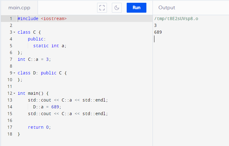
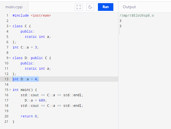
Static data members inherit REFERENCES to the parent!
Inheritance AT LEAST always inherits an interface (can optionally inherit implementation).
| Base implementation MUST NOT be inherited | pure virtual methods |
| Base implementation inherited by default | virtual |
| Base implementation MUST be inherited | non-virtual (and not shadow it) |
Shadowing
Whenever the member (function or variable) name is used in any form (even with different argument types or signatures), the parent member with the same name will be hidden. The behavior is called shadowing, and it applies unless you’ve overridden ALL versions (signatures) of virutal parent methods which shares the same function name mentioned in child.
- Any non-overriden method with the same name as the parent appearing in the child will shadow all parent methods with the same name regardless of whether they are declared
virtualand overriden at child. - You can unhide parent methods with the same name (but different signature) by
using Parent::f(..)declared at the child class. - Shadowing implies there’s always one parent version and one child version stored separately under all conditions {static or non-static}x{function or variable}
- Static members don’t really ‘shadow’ because there’s only one global storage for each (parent and child) if you declare the same variable name again in the child. There’s nothing to hide because you cannot cast or slice a namespace! With static members, you have to be explicit about which class you are calling from with SRO like
Parent::varorChild::varso there’s no potential for ambiguities.
Overriding
Just like C, C++ uses static binding that takes the programmer’s word for it for their declared types, especially through handles. Overriding is a concept only needed when you plan to upcast your objects (child accessed through pointer/reference) to handle a broader class of objects but intend to the underlying object’s own version (usually child) of the methods (especially destructors) called by default.
We do this by declaring the parent method virtual and implement the child versions (must be of the same function signature). Overriding only make sense for non-static methods because
- data members cannot be overridden (it’d confusing if it’s possible. We down-delegate functions/behavior but not the data/state). It’s better off hiding data members behind getters/setters to declare the intention.
- static members and methods behaves like static variable/functions (living in .data or .bss) using namespaces, so we can only refer to them with SRO by the class names like
Parent::f()andChild::a, not a class type likeParent p; p.f()andChild c; c.a. There’s no objectcfor you to upcast toParentso there’s place for polymorphic behavior.
Overriding involves leaving clues in objects so the upcasted references can figure out the correct methods of the underlying objects to call. In C++ it’s done with having a vtable (pointers to overridable methods, often stored in .rodata with string literals) for each class in the hierarchy and each object contains a pointer to the vtable that matches its underlying class.
[38] virtual only applies to methods’ signatures (function name and the data types in the argument list). vtable do not keep track of argument’s default values (if assigned) for efficiency (it’ll always read the static upcast, aka parent methods’ default values).
Classes (after considering inheritance)
Design relationships
- class behaves through public methods
- Inheritance at least always inherits an interface
- IS-A relationship is done with public-inheritance
- … (incomplete, will update later)
![]()