I received an Agilent N9340B 3Ghz Handheld Spectrum Analyzer with a note that it passes all self-tests but does not respond to input signals. I took the gamble that it’s the RF input connector got disconnected somehow.
I opened up the case and noticed that the 40Mhz cable was unplugged, so I was half-correct. I connected it and got a signal at the precise frequency, but the amplitude doesn’t look quite right. It’s around -20dB off. When I scanned it across the full 3GHz band, I noticed the amplitude roll-off when I scan below 800Mhz, and I got very little signal left when I get to somewhere near 10Mhz.
I tried running a user calibration with a 50Mhz CW source but it failed amplitude calibration. Apparently the unit is not fully working. No self-test errors though.
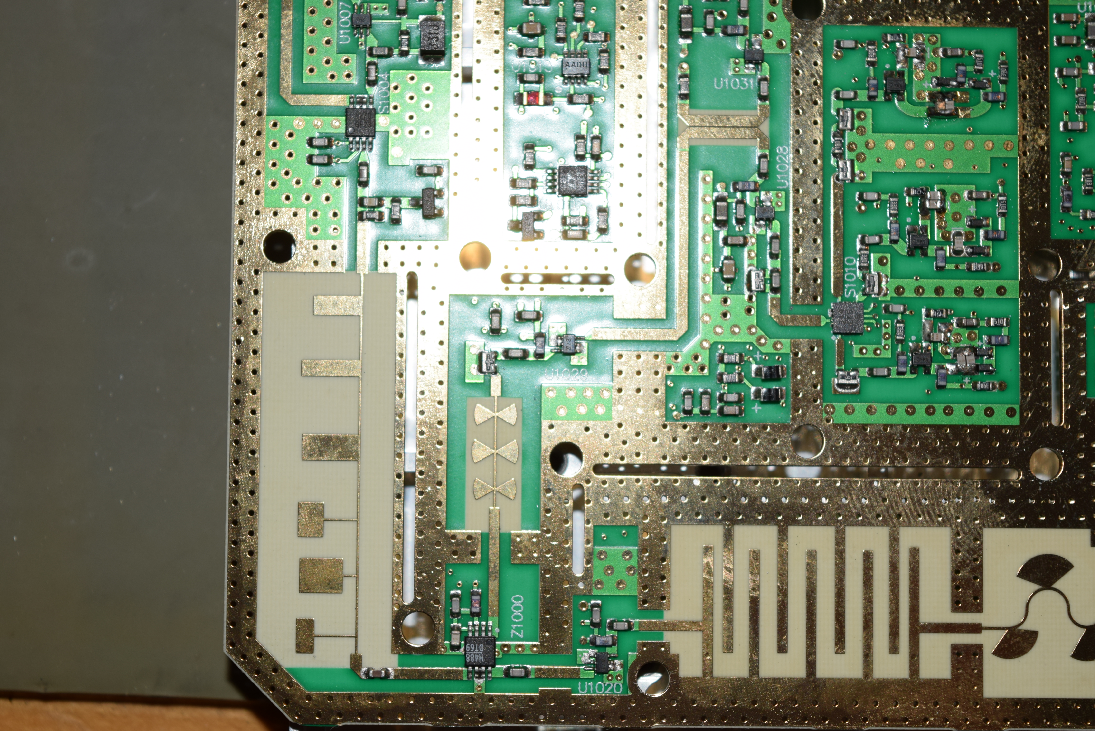
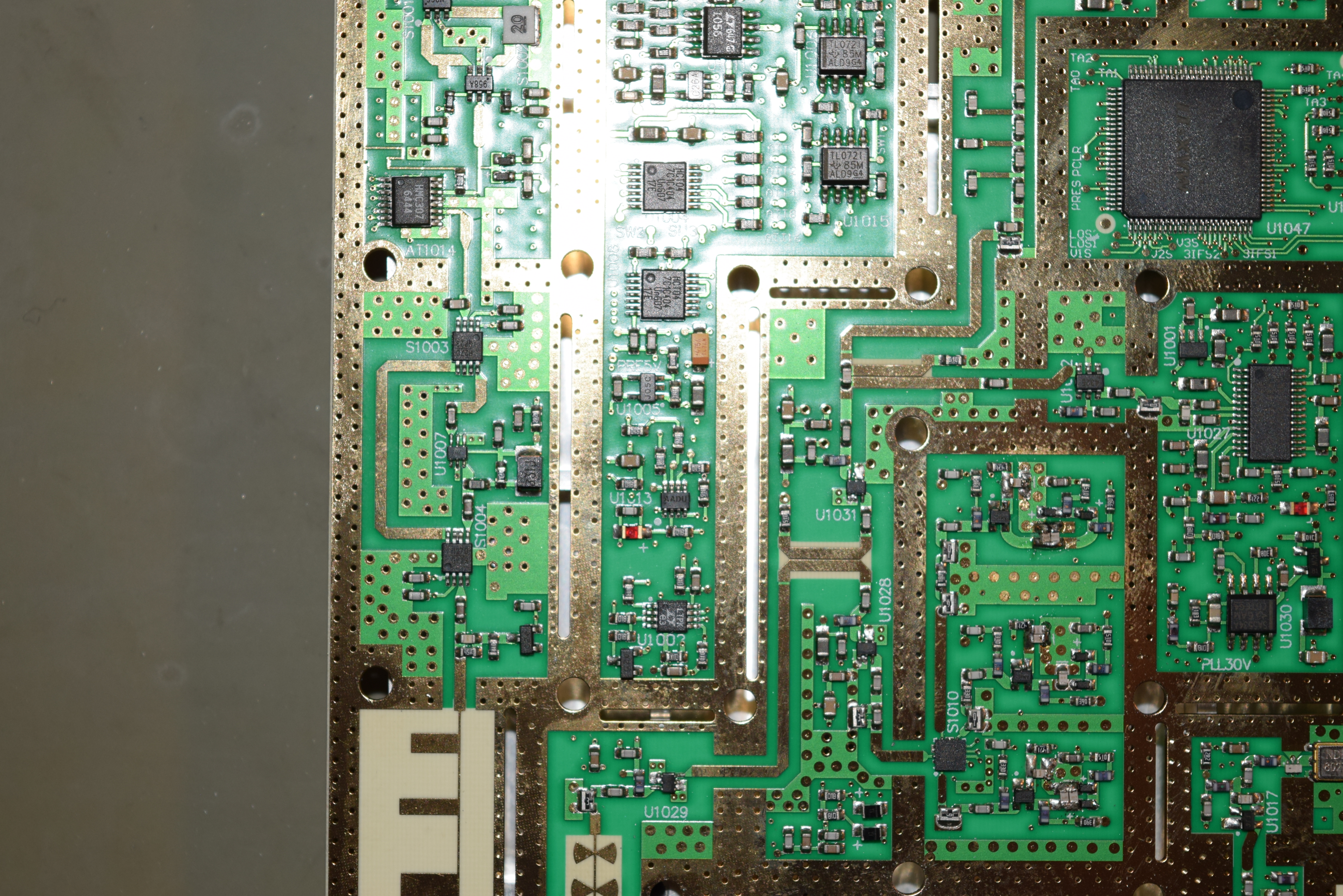
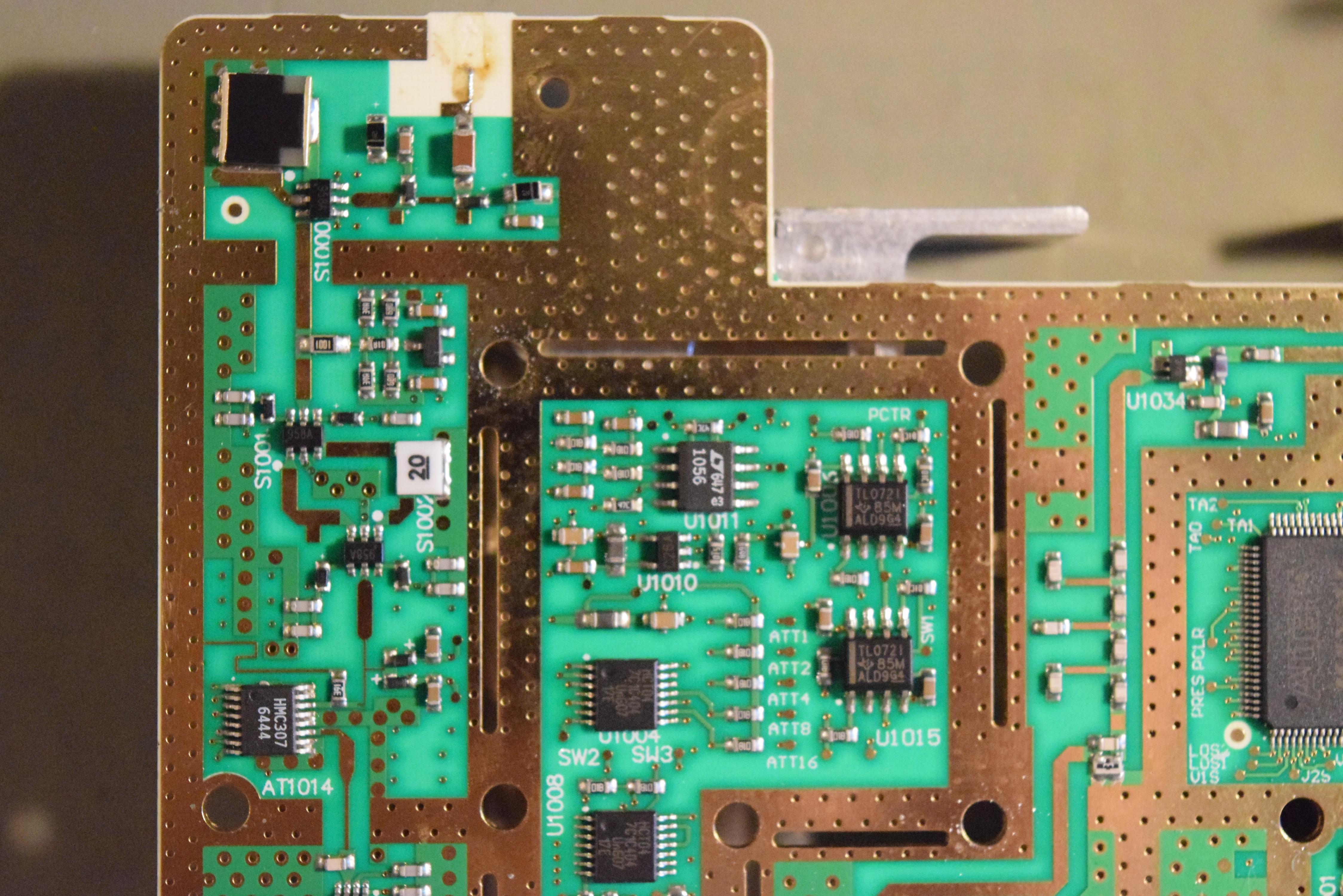
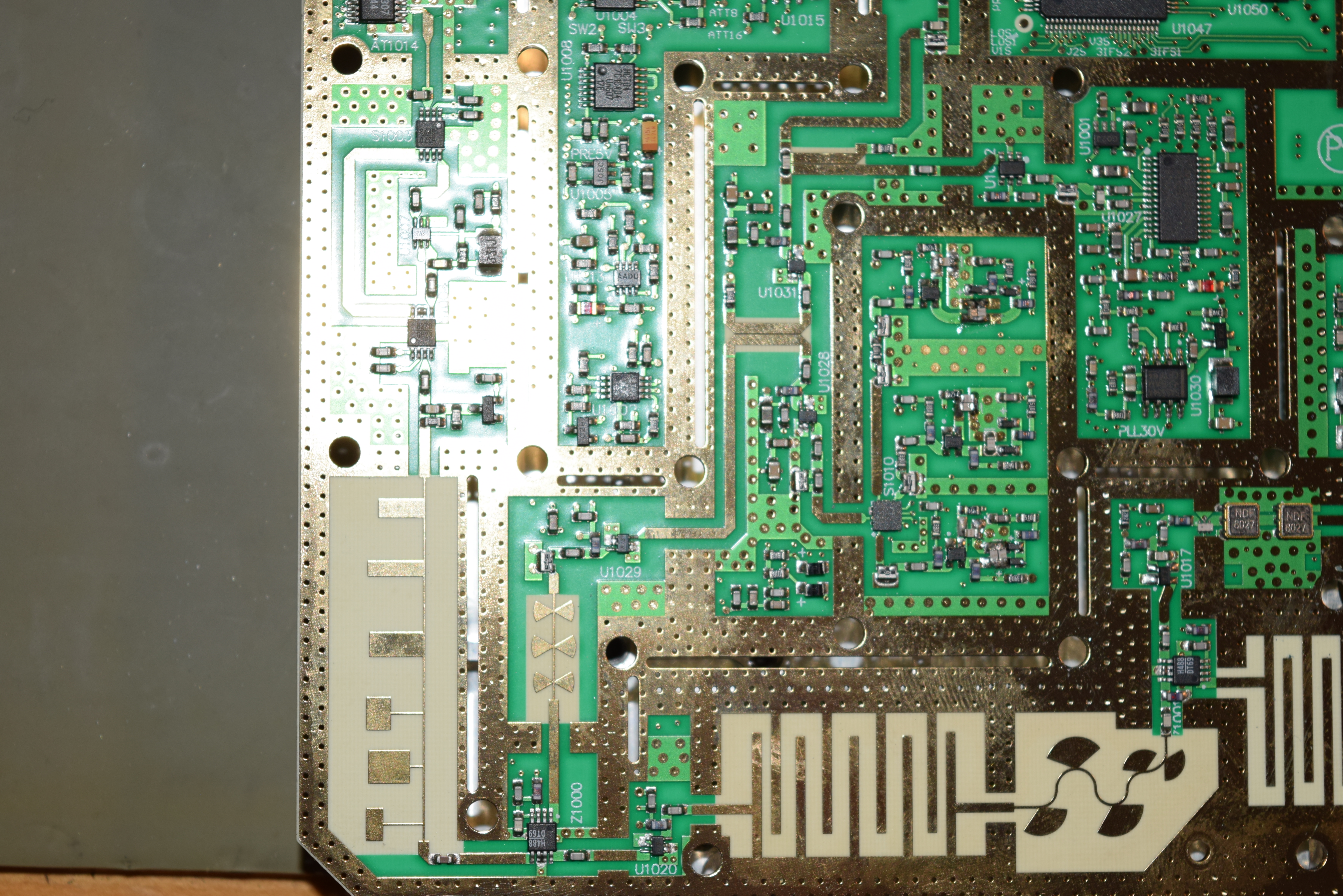
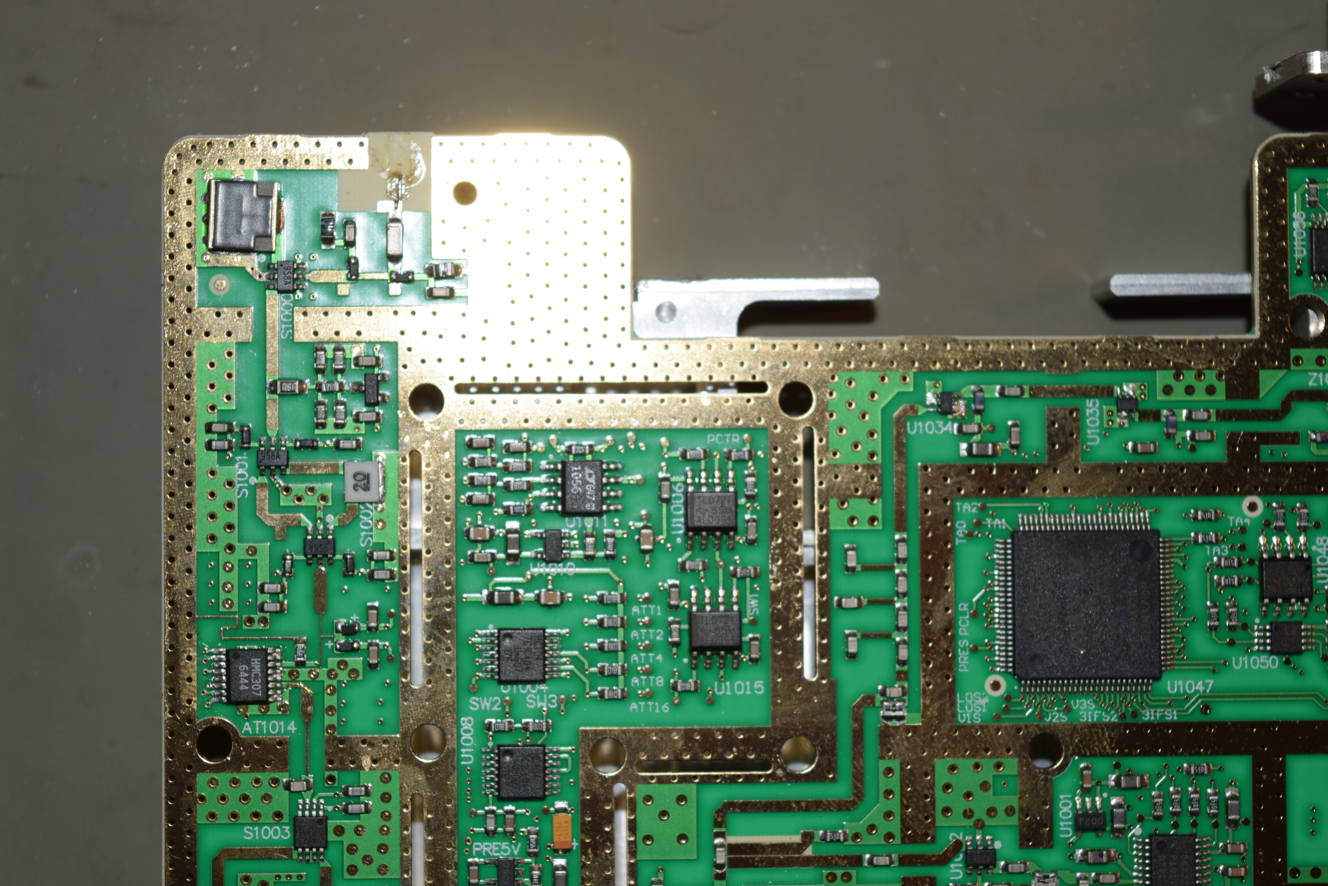
So I opened up the unit and the RF section. The front side of the board doesn’t have any visible signs or unusual smells, so I suspected the improper gains is caused by the input attenuator HMC307:
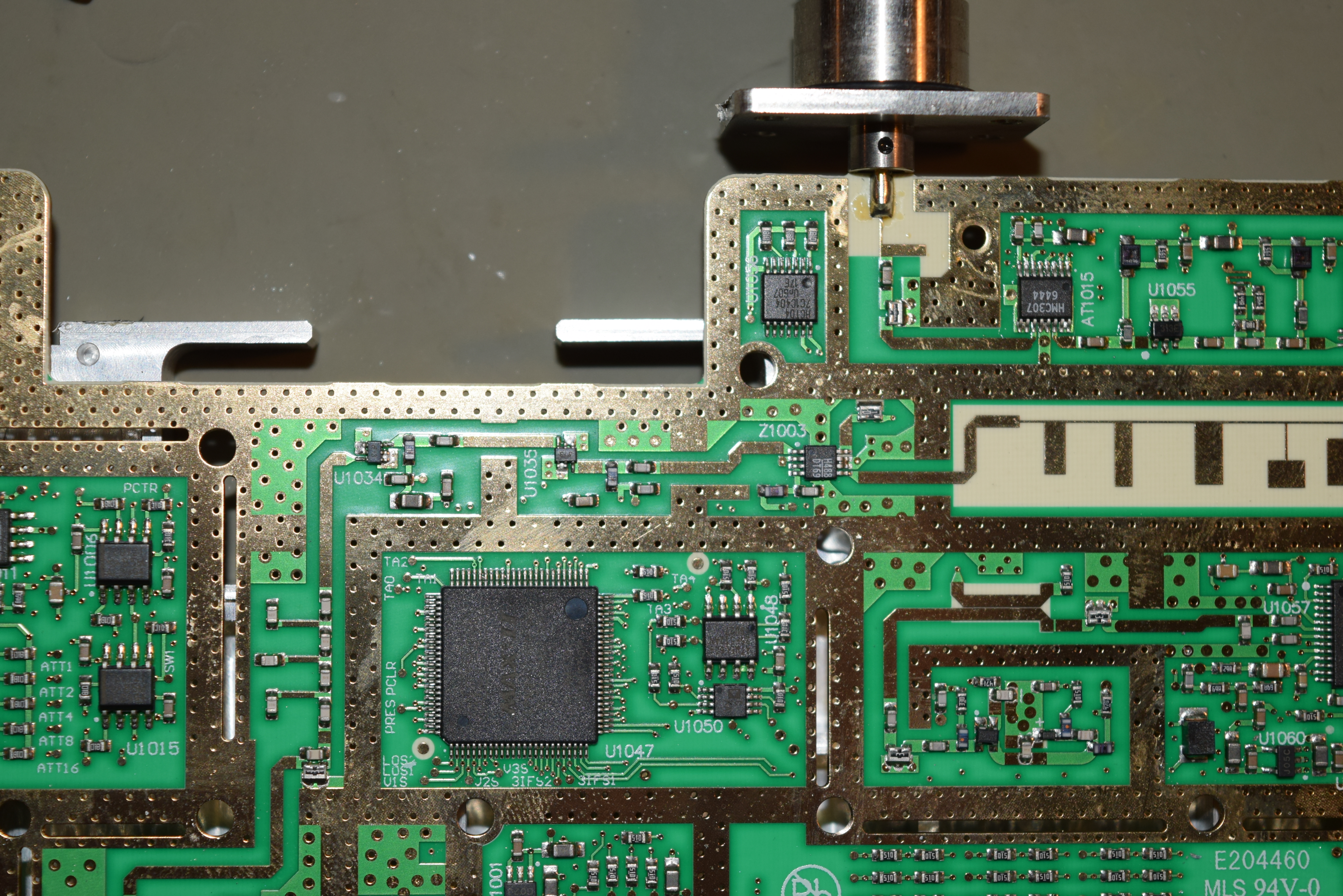
I was about to order the chip, but because of the lead time, I decided to just take a picture of everything and analyze it off-line:
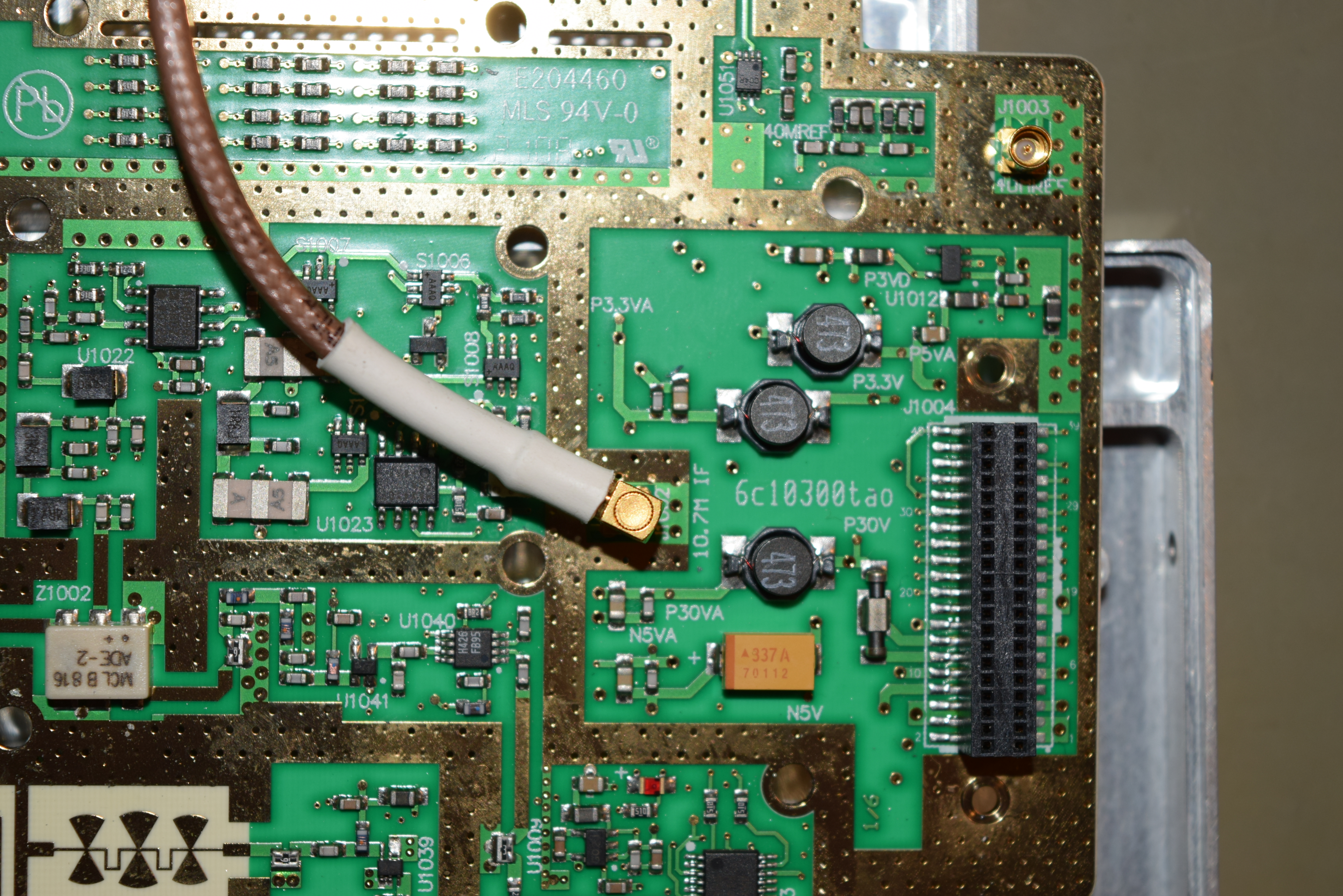

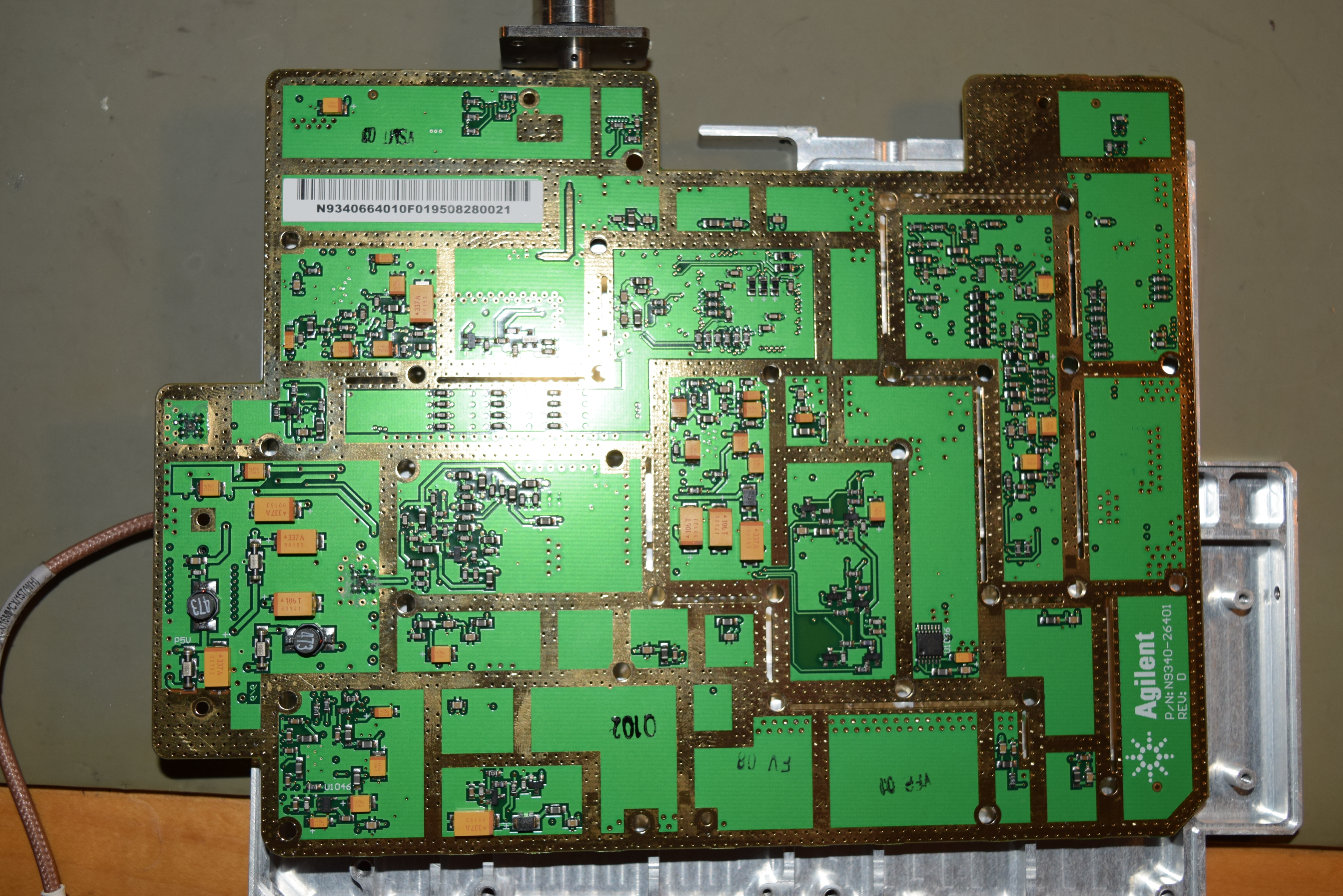
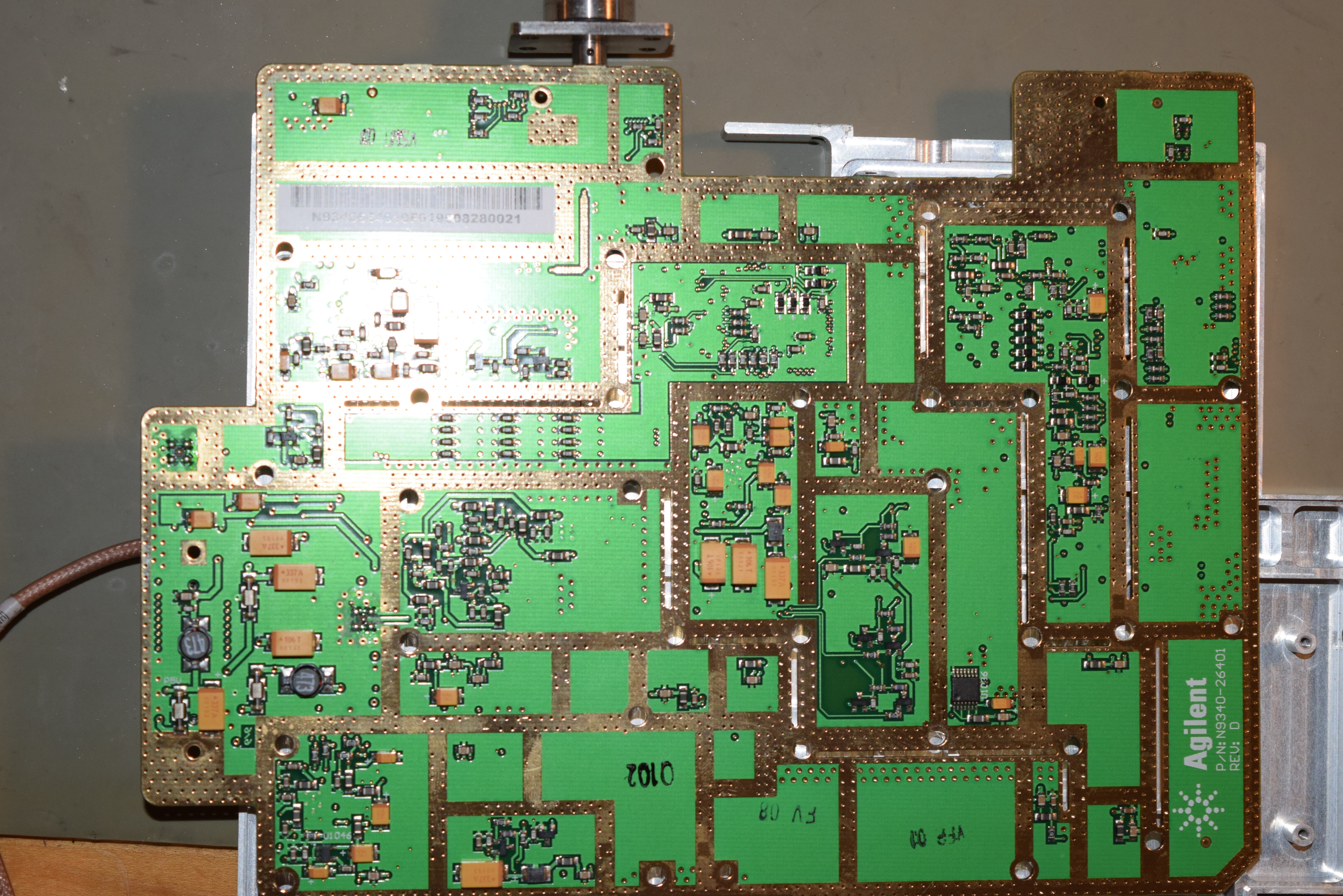
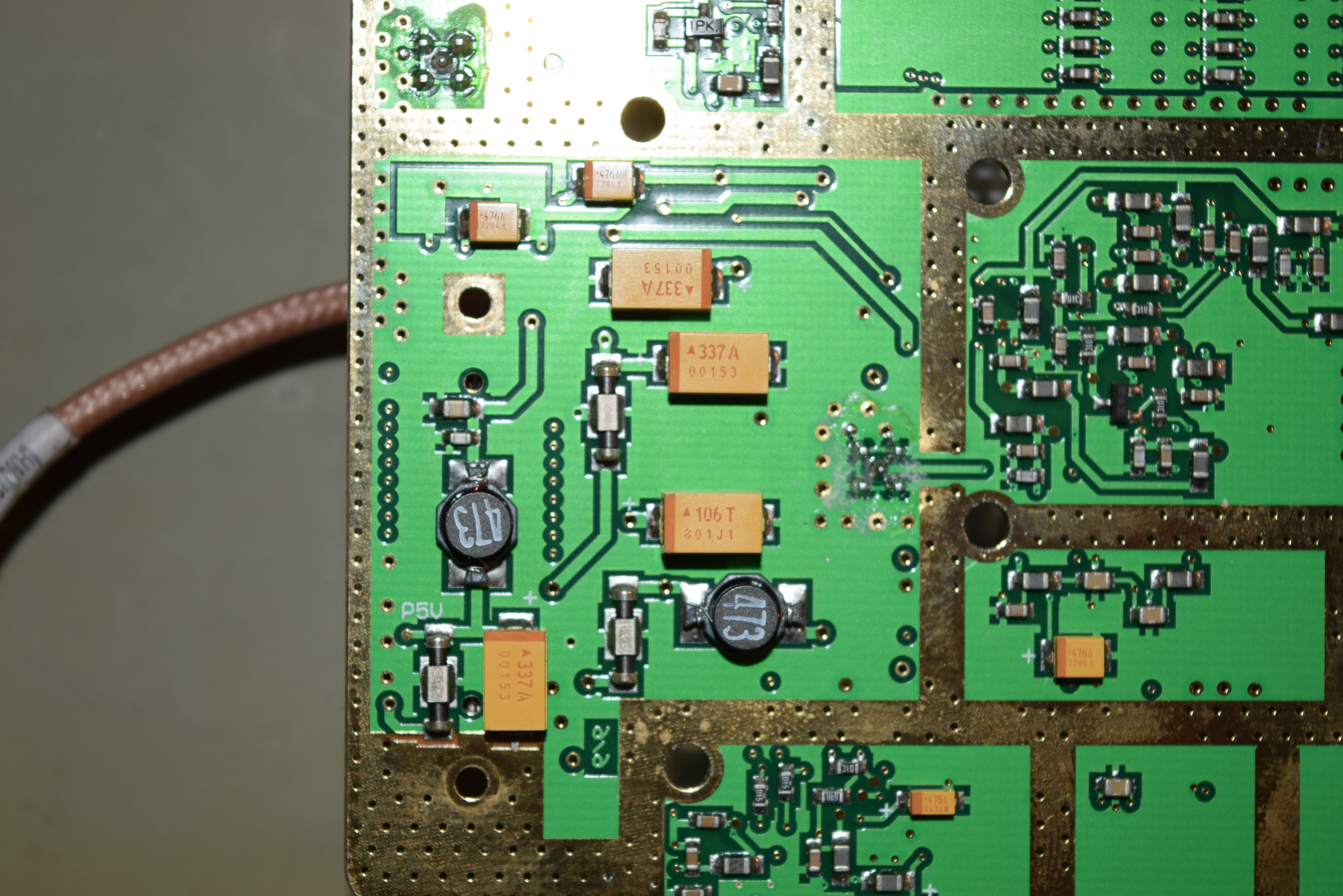
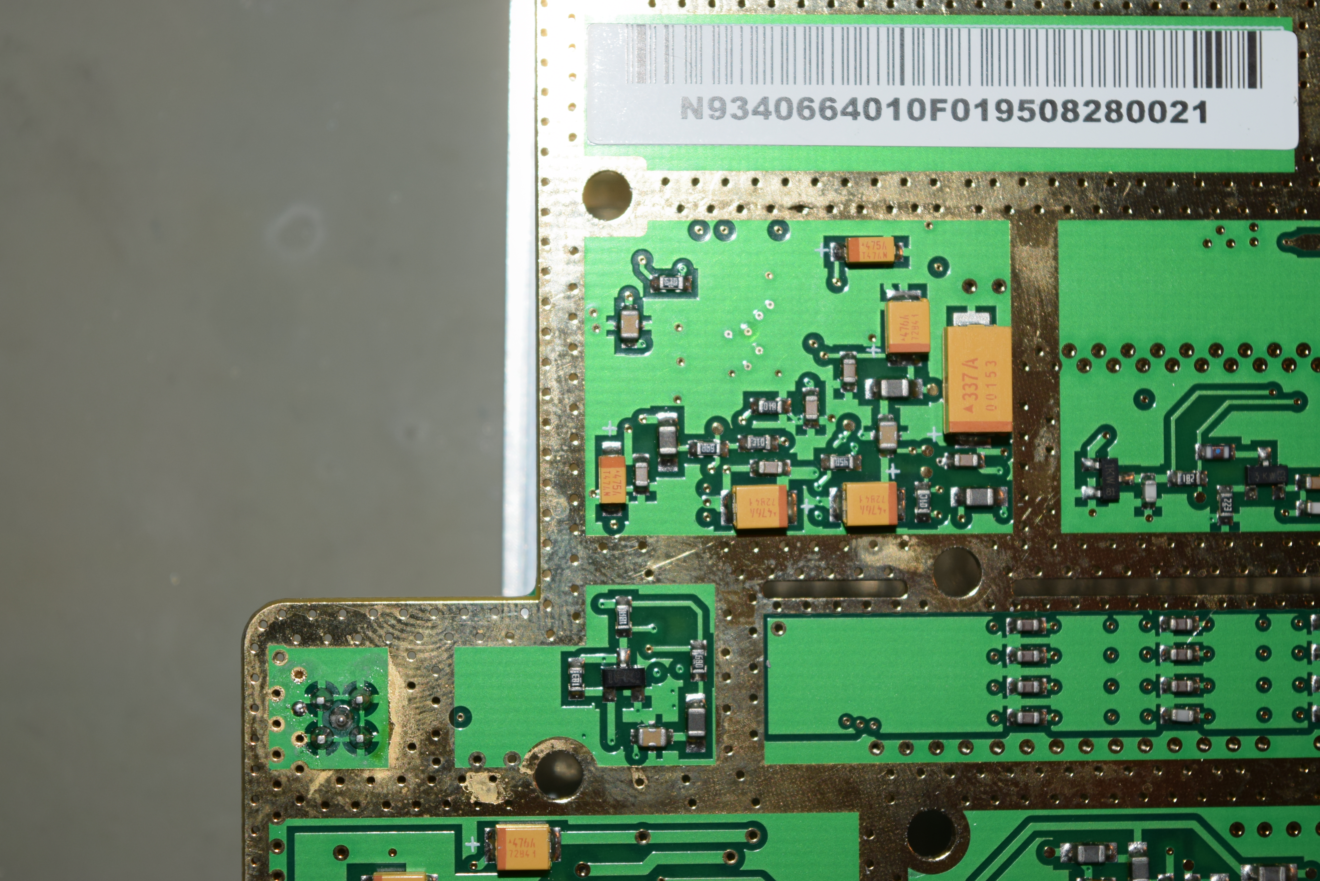
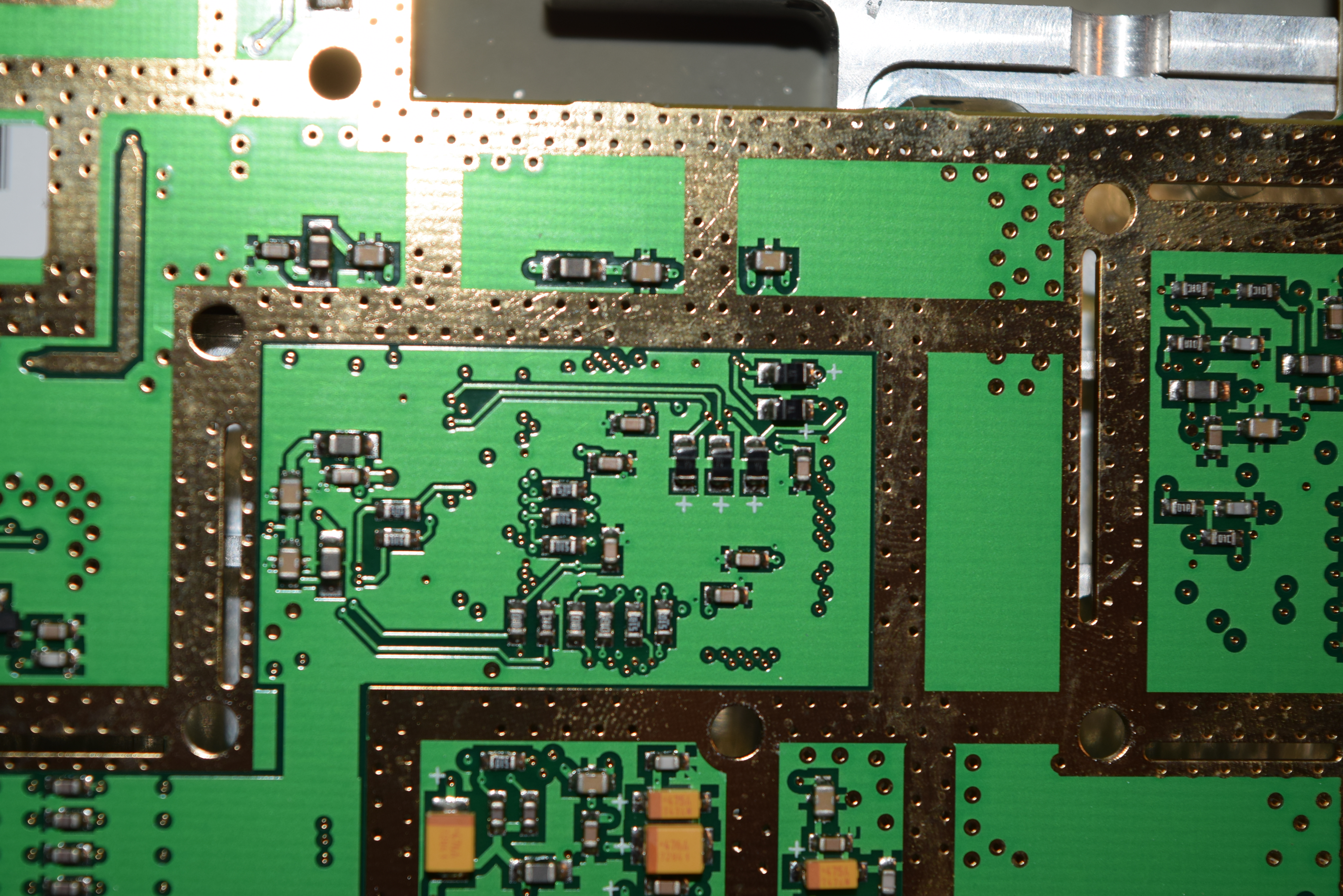
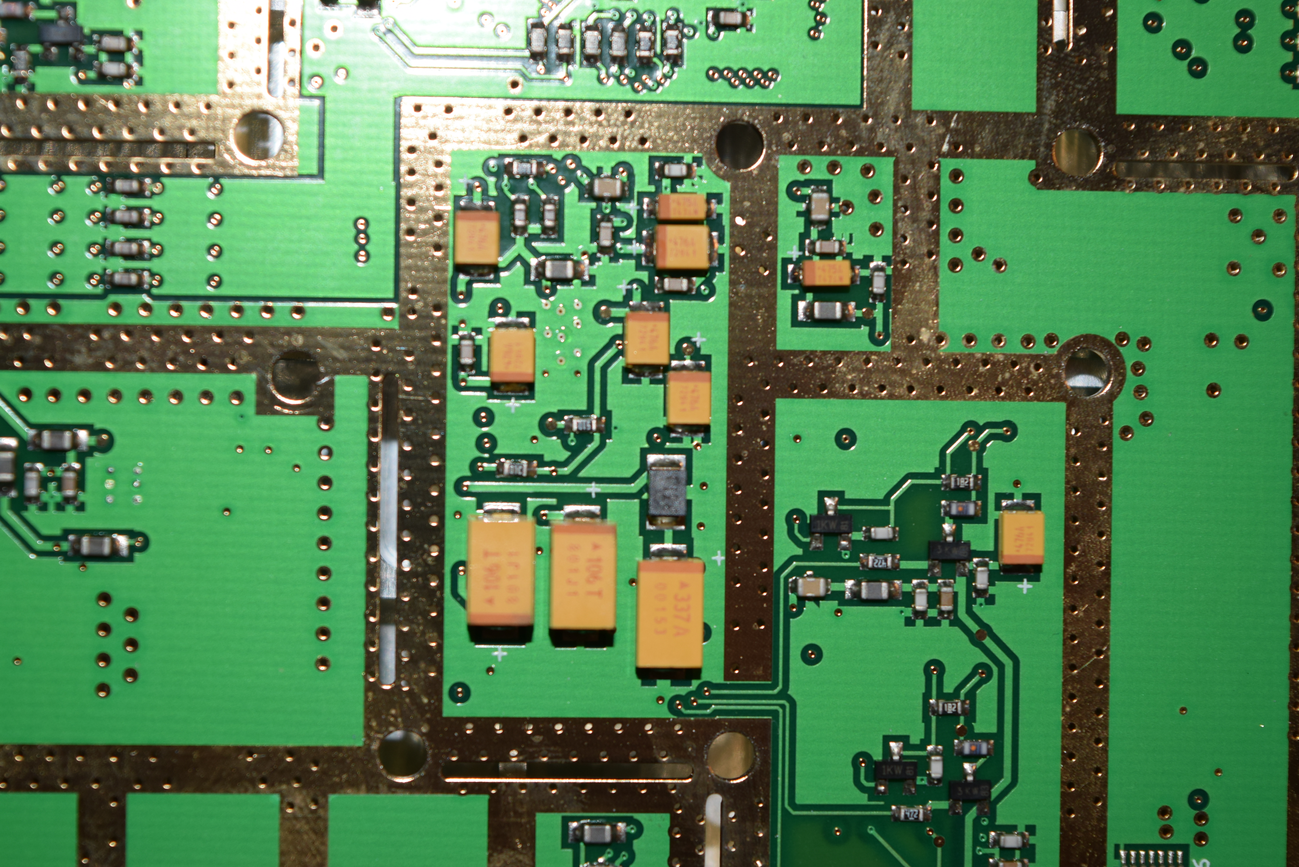

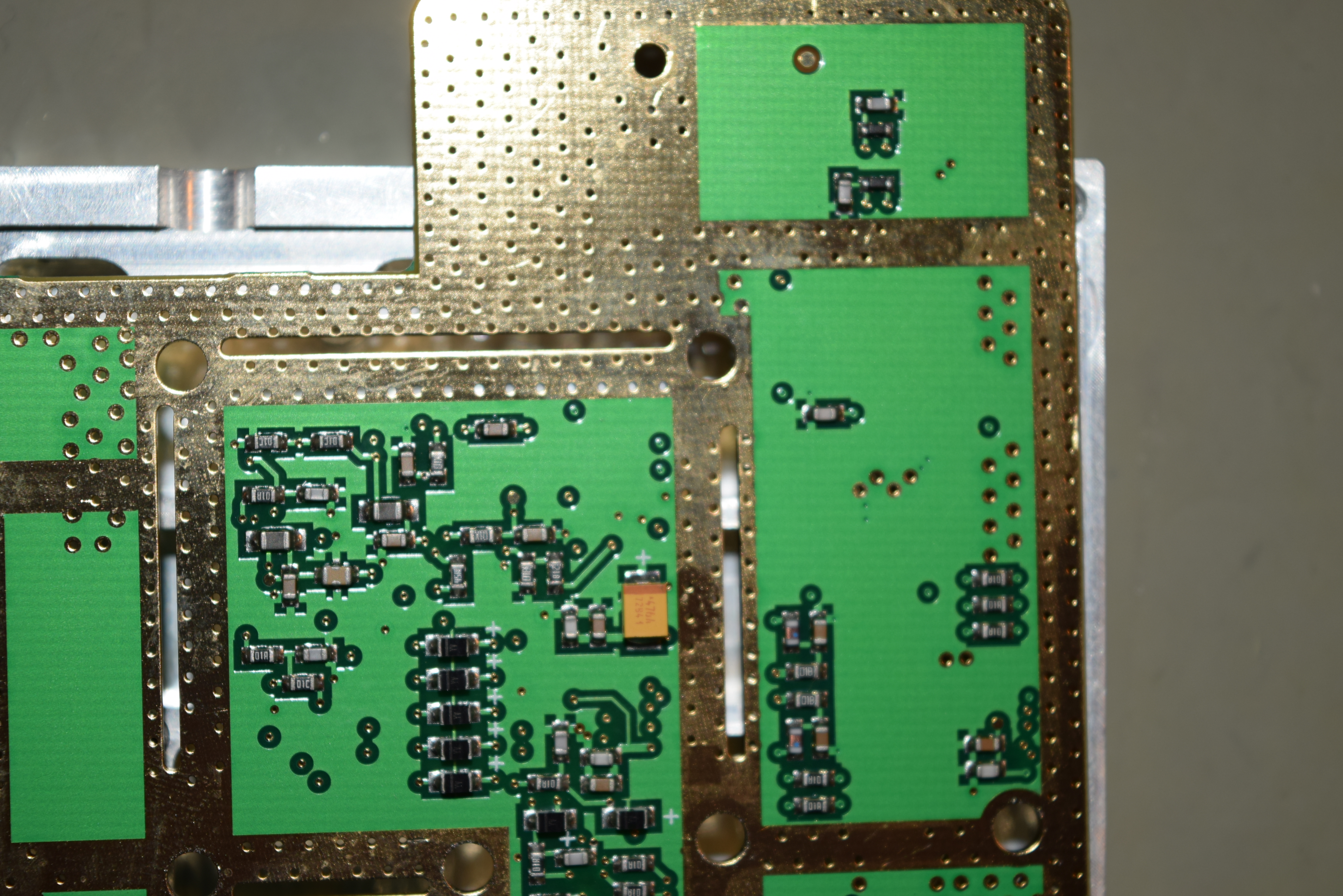

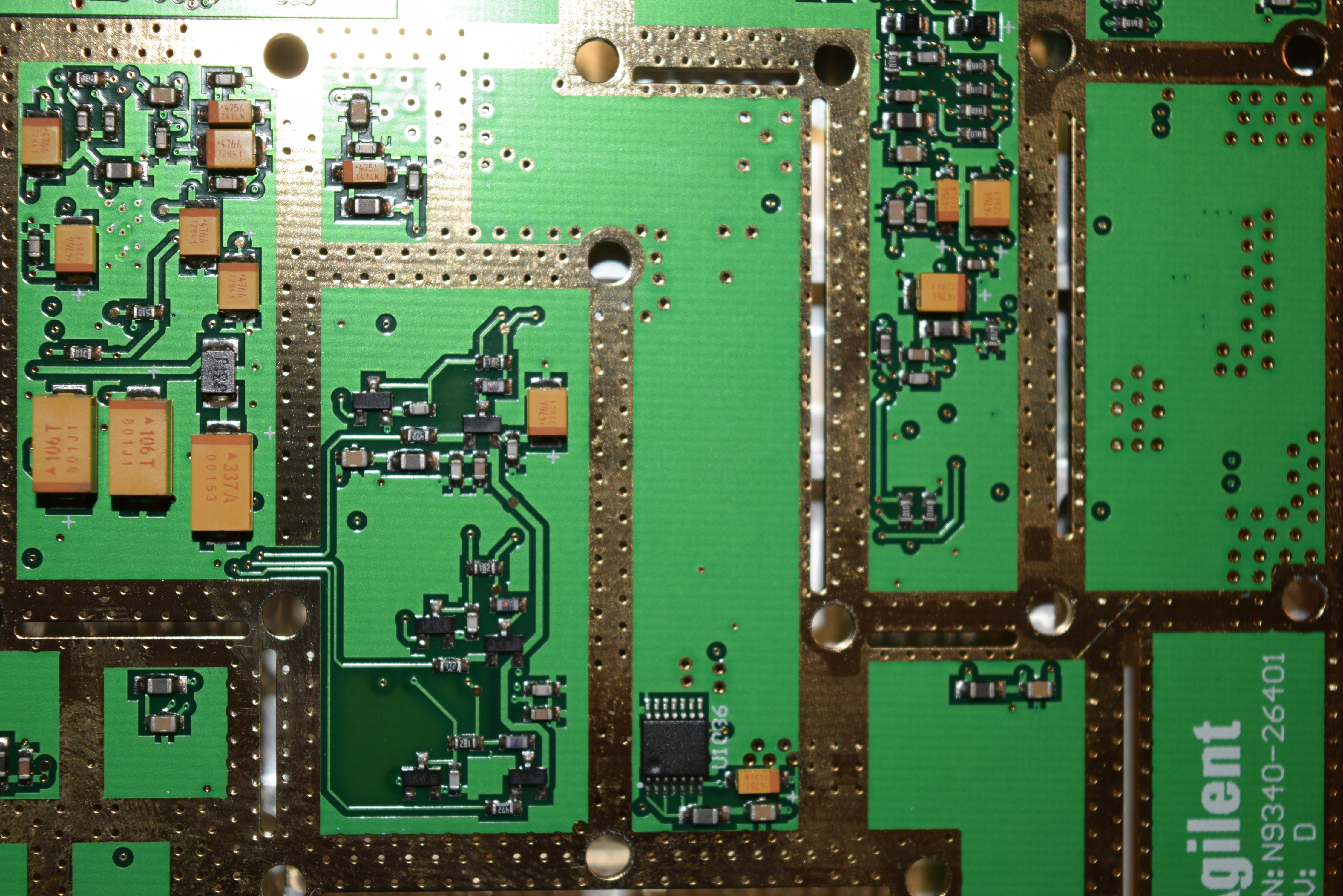
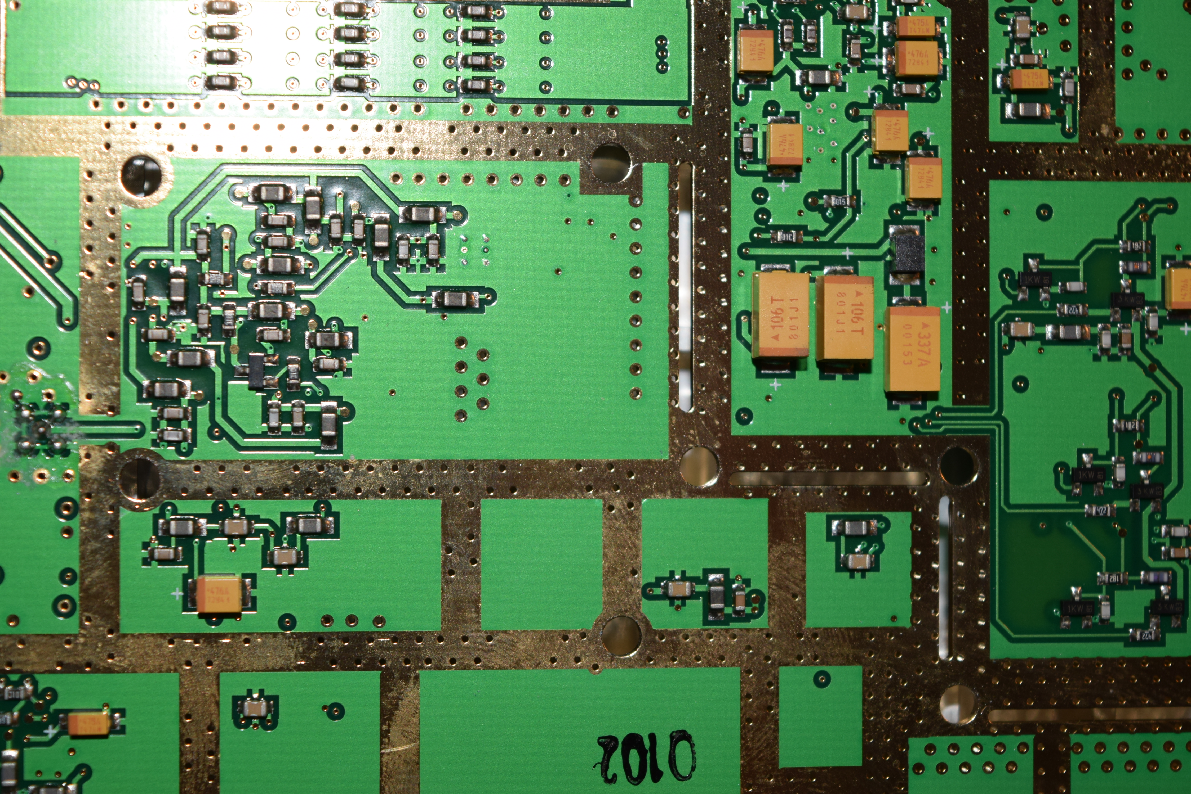
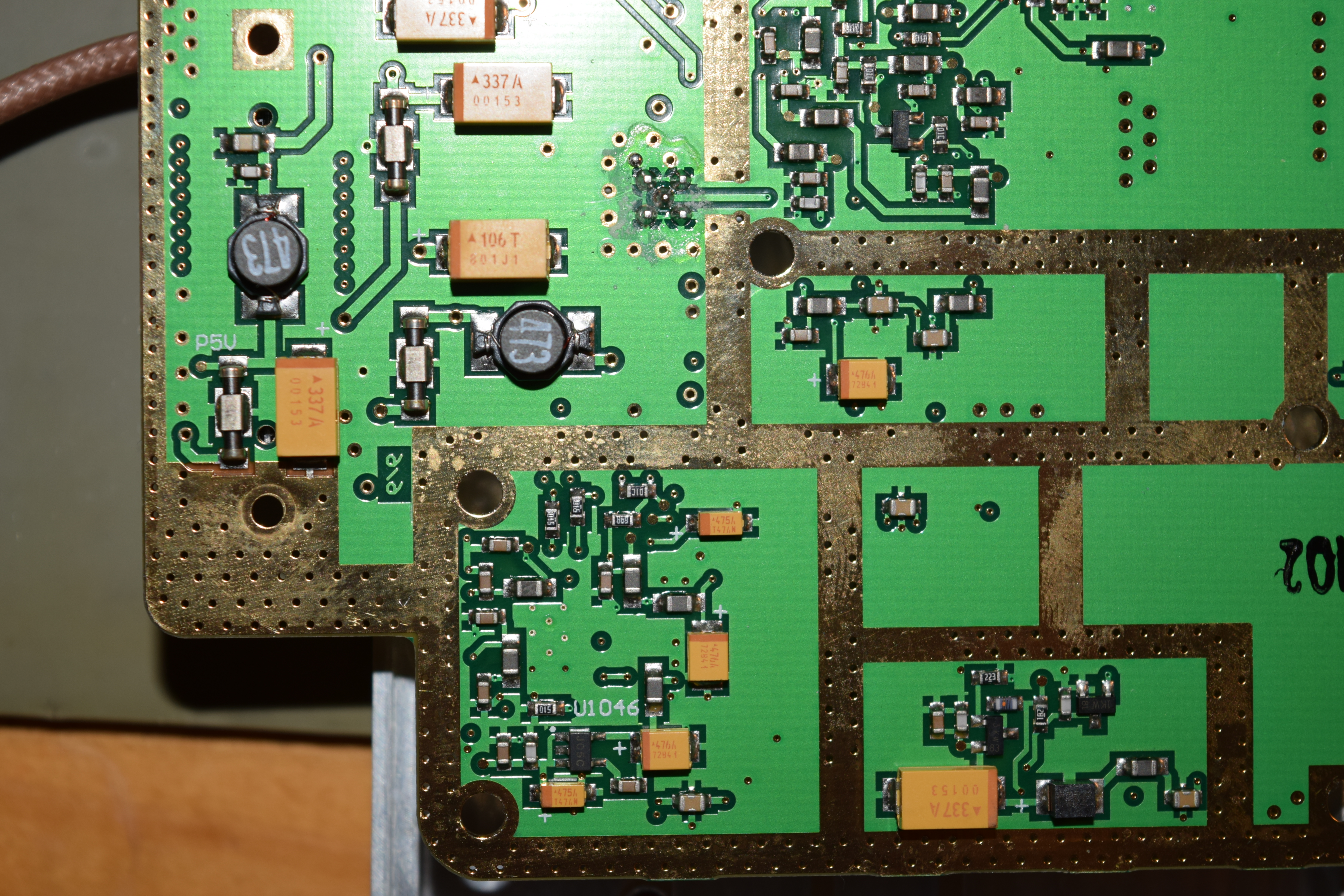
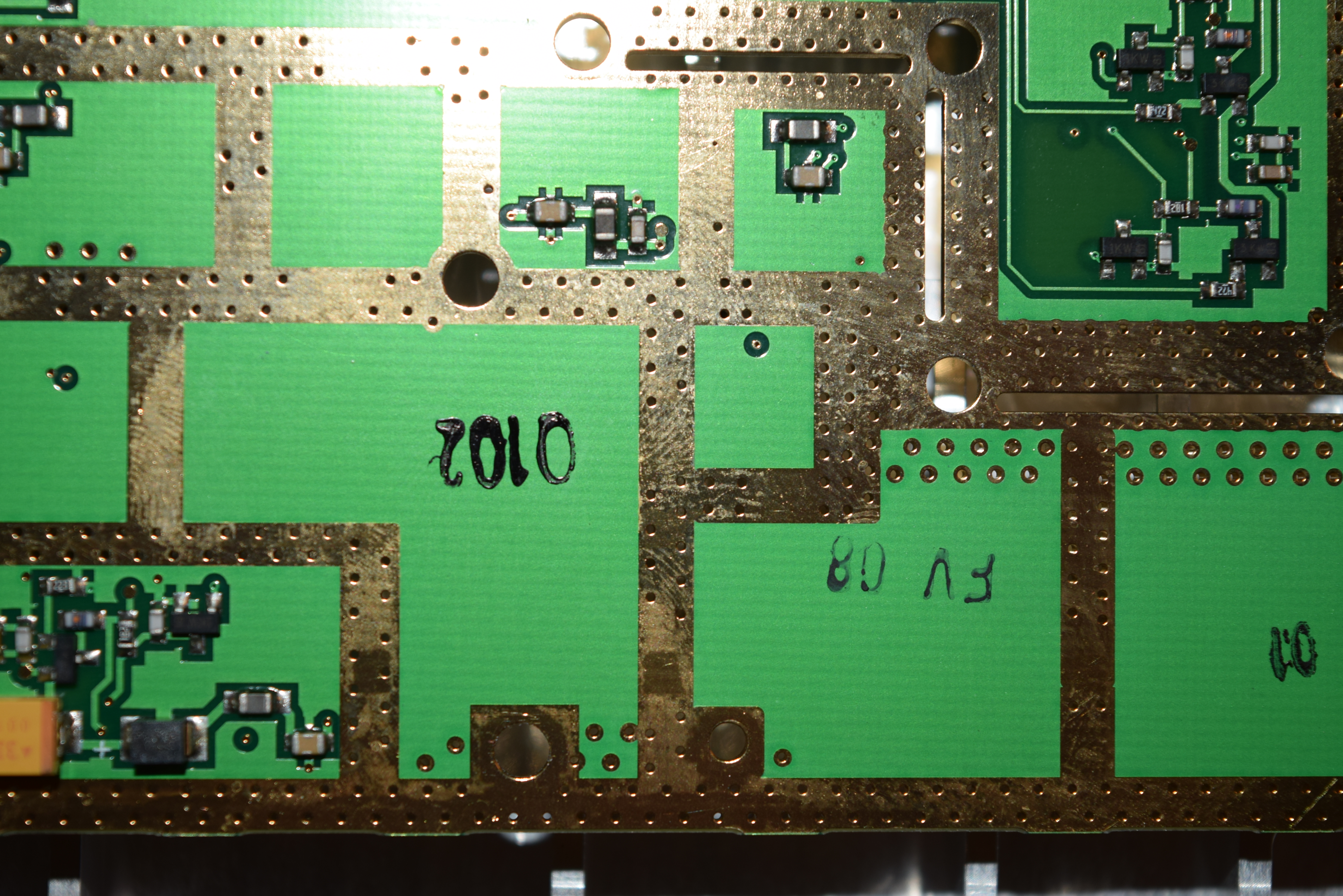
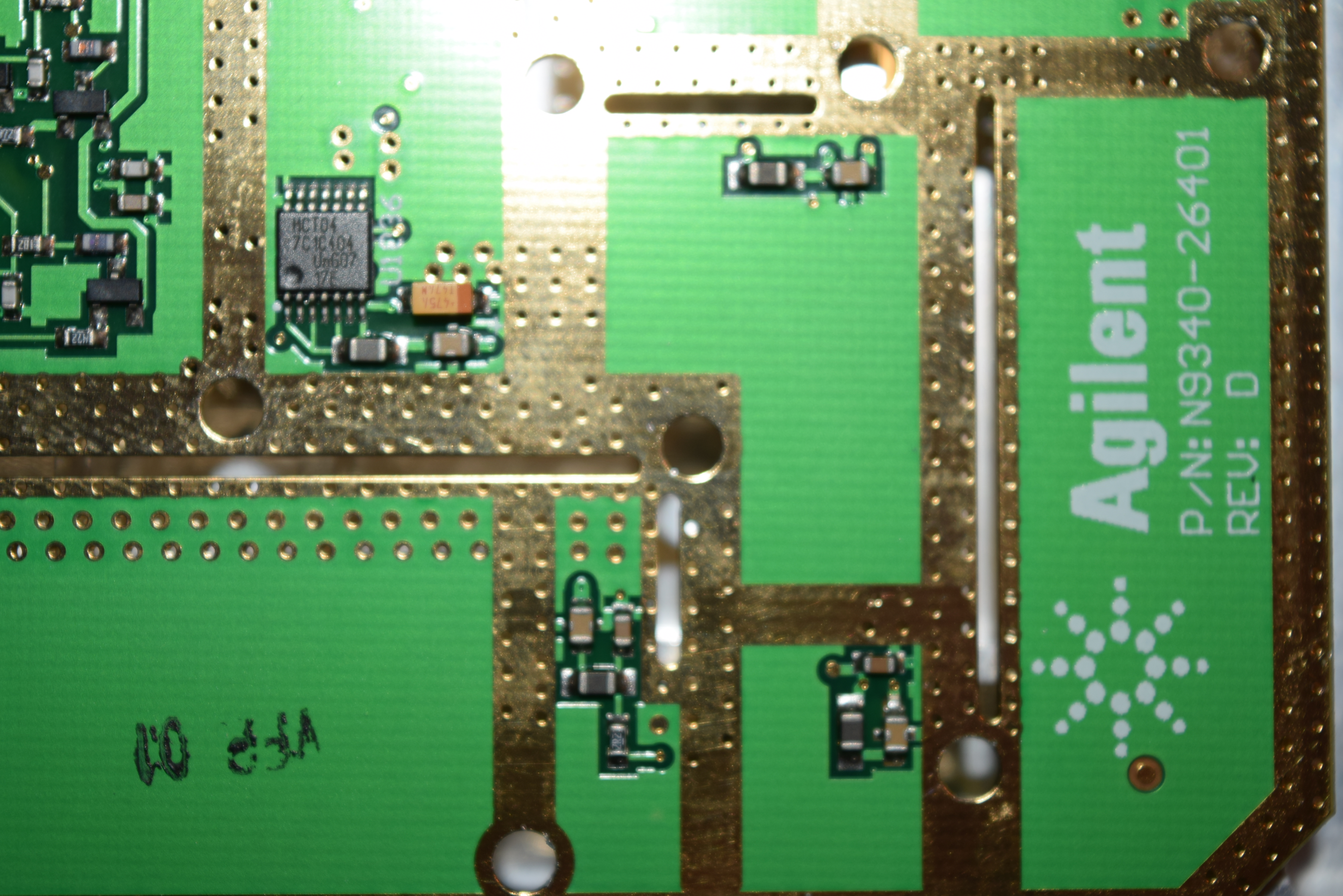
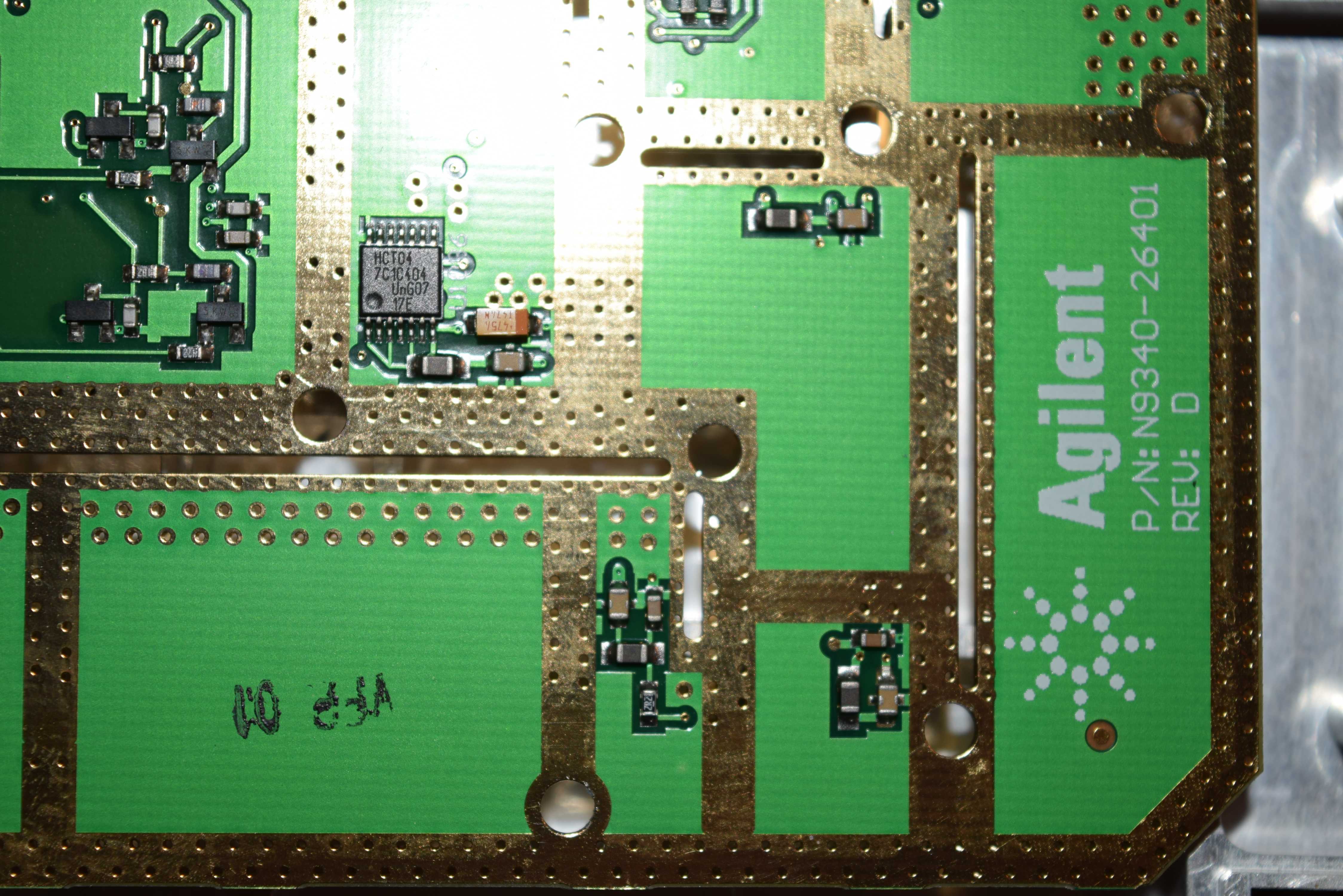


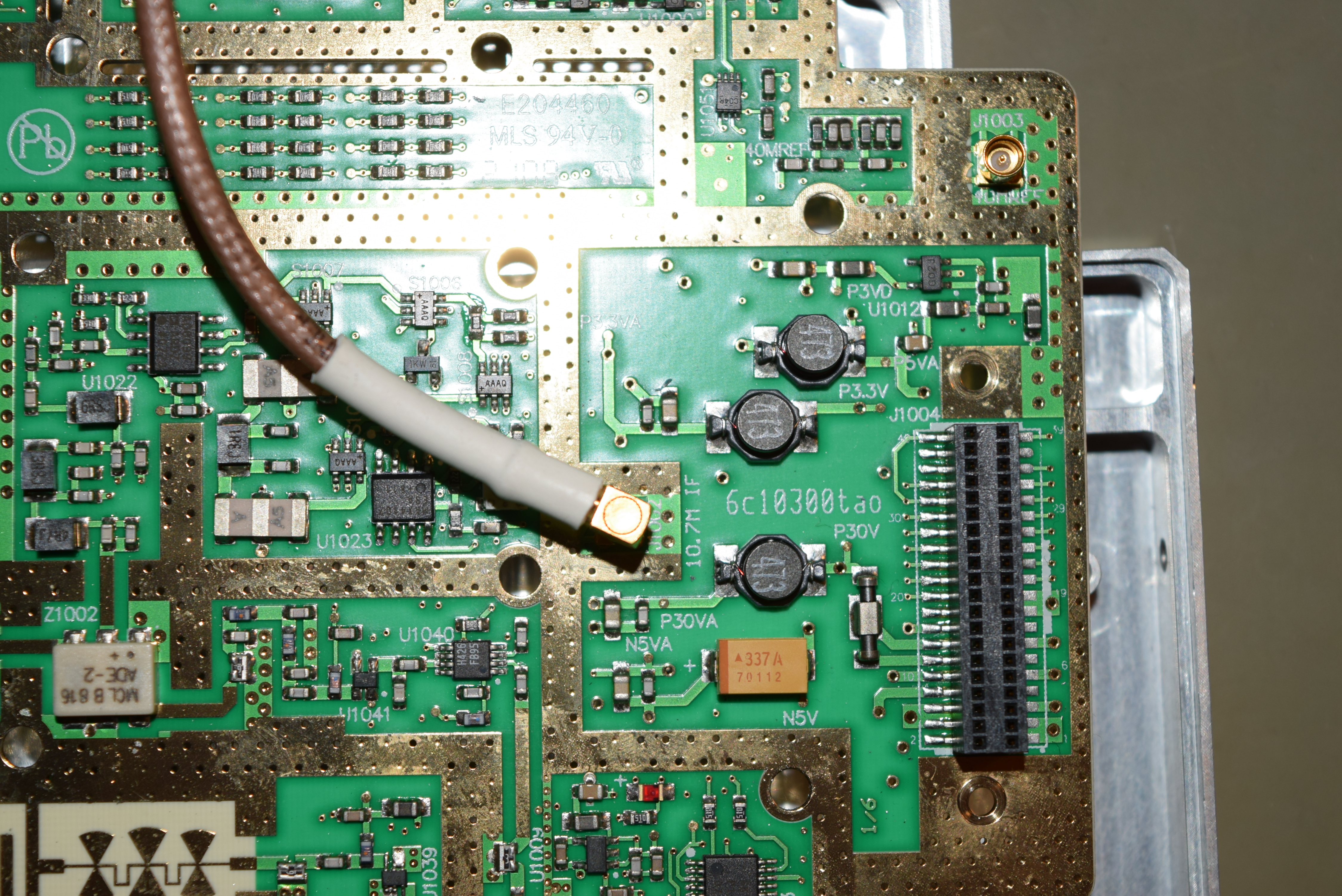
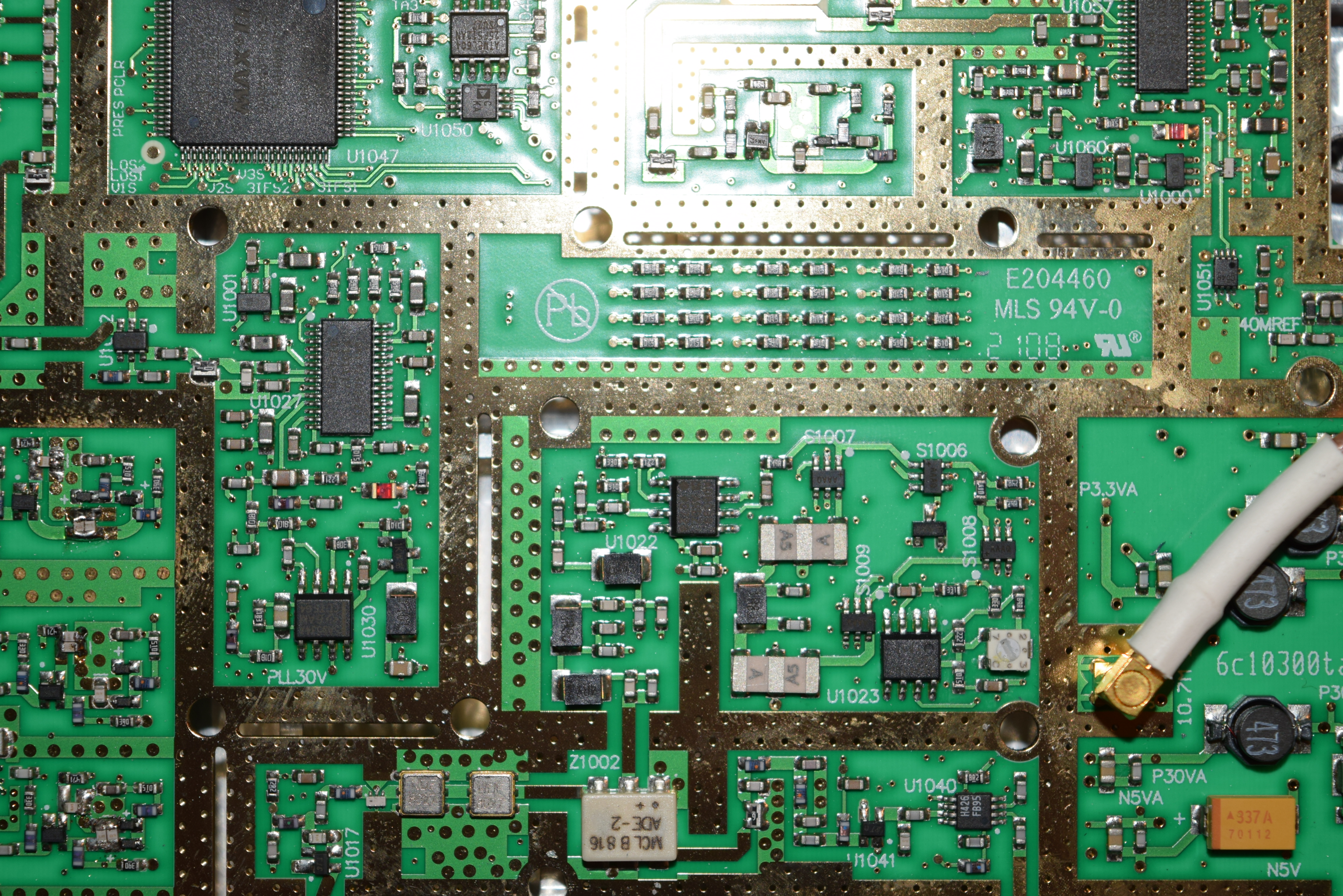
After removing the screws holding the N-type terminal so I can get to the back side of the board for taking pictures, I noticed the RF in connector just fell off the board with the pad:
That means the RF in is not touching the board! I resoldered the connection after I put the board and the connectors back to the RF module slab. Once I put unit back together, I turned it on again and everything works perfectly! The power level is flat and within 1dB of what my 8648C pumps out. I did the user amplitude calibration again, it passed, and everything was spot on!
![]()