My router only supported Merlin (Tomato) firmware up to 380.70_0 (2018-04-08) and there are no more updated from that branch.
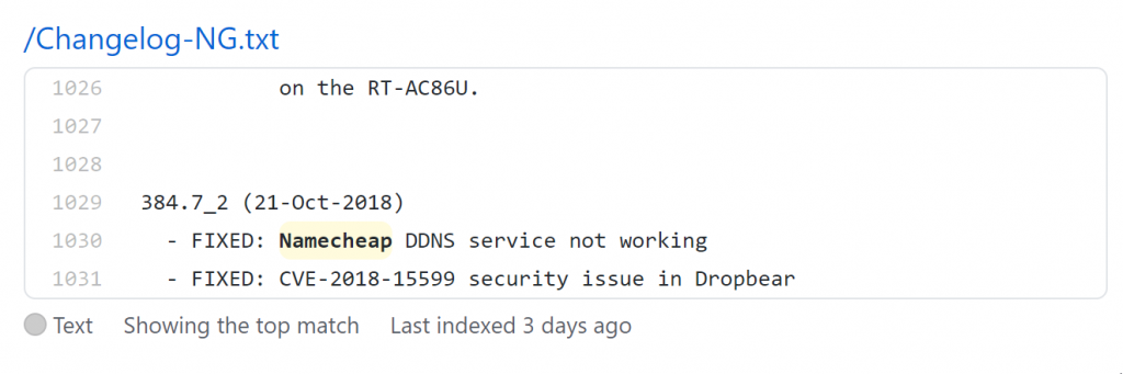
Turns out the Namecheap DDNS client is not working. I searched its source code at Github for “Namecheap” to see if I can fix the HTTP 400 error (seen in router log) using “in:file” hoping to see if I can fix the bug myself (since it’s just a simple REST API, aka URL call) command and found this:
It means Asuswrt-Merlin (Tomato)’s firmware’s Namecheap DDNS service is broken UNTIL 384.7_2, which is for newer routers than what I have.
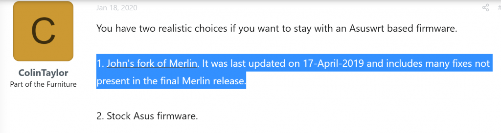
I compared the “namecheap” keyword search for the two versions and it seems like they are written very differently, so it might not be worth the effort to fix the obsolete Merlin branch. Doing a bit of additional search and discussions about John’s Merlin fork from the early days are still updated until 2019-04-17 :
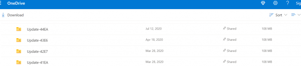
It took me a while to find John’s forum post to get to the said 2019-04-18 release. The download link he provided has more updates up to Update-44EA (2020-07-12) and it still worked on my old router, so it’s not just the Update-39L3 previously discussed in the forum:
Do not get discouraged when John’s Merlin fork says version 374.43 instead of 380 (a lower number). All updates, even the latest one from John still use 374.43, which I suppose it’s to mark when the two code branches part ways. It’s not an older version.
This meme is spot on about my expertise in HP/Agilent/Keysight Infiniium Oscilloscopes. It might take me 30 minutes to put on the automation I’ve created to fix a specific issue, but nobody with just one non-functioning unit in front of them can figure out the right steps even if they worked on it for months. Writing the automation itself turns out to be the least of the bulk, and it’s still more time than one is willing to spend writing the scripts or performing the undocumented procedures manually.
Many of my know-hows were acquired to be used once or twice. I solve problems that are not seen before. I always start with doing due diligence researching what has been done, rather than jumping to reinvent the wheel. If I confirmed that it’s an unsolved problem, I’ll start inventing.
Once I figure out the details I often automate the workflow, document it, and move on to something else.
That’s why for consulting, I often quote high hourly rate for the first few hours and taper it down for more complex projects (keeping the project short). It’s to make sure we don’t have incentives to waste each other’s time and focus on solving your problem as fast as I can figure it out.
Play store: F-droid (Bonus: many open source apps that are paid apps on Google store offer the full version for free on F-droid to encourage you to move away from Google Play), Yalp Store
Rob Braxman Tech (He knows about the nasty dictators like the Chinese Communist Party. Don’t think you are safe in America. The reach of the Chinese Communist Party Mafia, formerly known as the Chinese SOVIET Republic) is beyond our imagination.
Alternatives to Big Tech respecting privacy (for now)
Search (Google): DuckDuckGo
Browser (Chrome): Brave
Email (Gmail): see above (self-host) or ProtonMail (zero knowledge encryption)
Cloud (Google Drive, OneDrive, Dropbox, etc): see above (self-host) or use zero-knowledge encryption
Text/Chat (Whatsapp, Line): Signal App
Calling: Telegram has better voice quality than signal, but sometimes it has weird behavior on certain phones. Telegram does not have zero-knowledge proof, so it’s up to Pavel Durov (he’s usually good at not bending to totalitarians).
Alternatives to Big Tech that refuses to censor and manipulate users (for now)
Video (Youtube): Odysee (LBRY), Rumble
Facebook: MeWe
Twitter: Gab, Safechat, CloutHub has a crappy search feature, Parler now has PC bots patrolling and misfiring
Zero-knowledge encryption means the server have no access to the info you put in there as they are all encrypted and protected by a password which only you have (preferably use zero-knowledge proof so the owner of the server do not have any master keys to see your data: you lost the key and the data is practically gone forever)
I tucked away my PC a little away from my workstation desk and the power switch is located at an inconvenient location. I tried to keep the wiring minimal so I’d rather not wire a dedicated ATX power switch onto my desk.
Unfortunately my motherboard does not support turn on by USB keyboard, and I’m not ready to upgrade because I am using it to test PCI data acquisition cards and it’s the fastest one that has 4 PCI slots and they are hard to find nowadays.
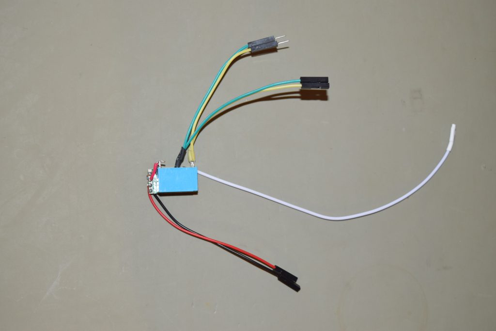
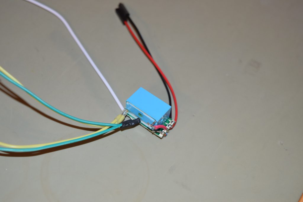
I found a $2.5 wireless module on eBay that claims to switch LED lamps which works on the standard 433Mhz channel and it replicates momentary switch pattern and can operate on 5V (My motherboard is new enough to have 5Vsb from onboard USB header).
Note that there’s a schematic picture which switched the colorings of the input and output pairs. The actual wiring color is correct.
Initially I was tempted to get the built-in relay version, but I was worried about the current draw from 5Vsb and those are 12V relays., not to mention the footprint is much bigger (the one above is 22.5mmx 11mm x 8mm).
I thought I can figure out with some sort of BJT switch instead of using a relay that has a much bigger current draw requirement, but I realized it’s a pain in the ass because the output is ‘floating’ differential. The OUT- does not tie to the power ground (it’ll short out the unit when I tried to. That’s why I added quotes to ‘floating’ because it’s only relative to OUT+). I also measured OUT+ which is +5V with respect to power ground.
I tried to power a LED and it only works if current flows from OUT+ to OUT- so it’s really sinking current from source power to do that, and it’s unidirectional.
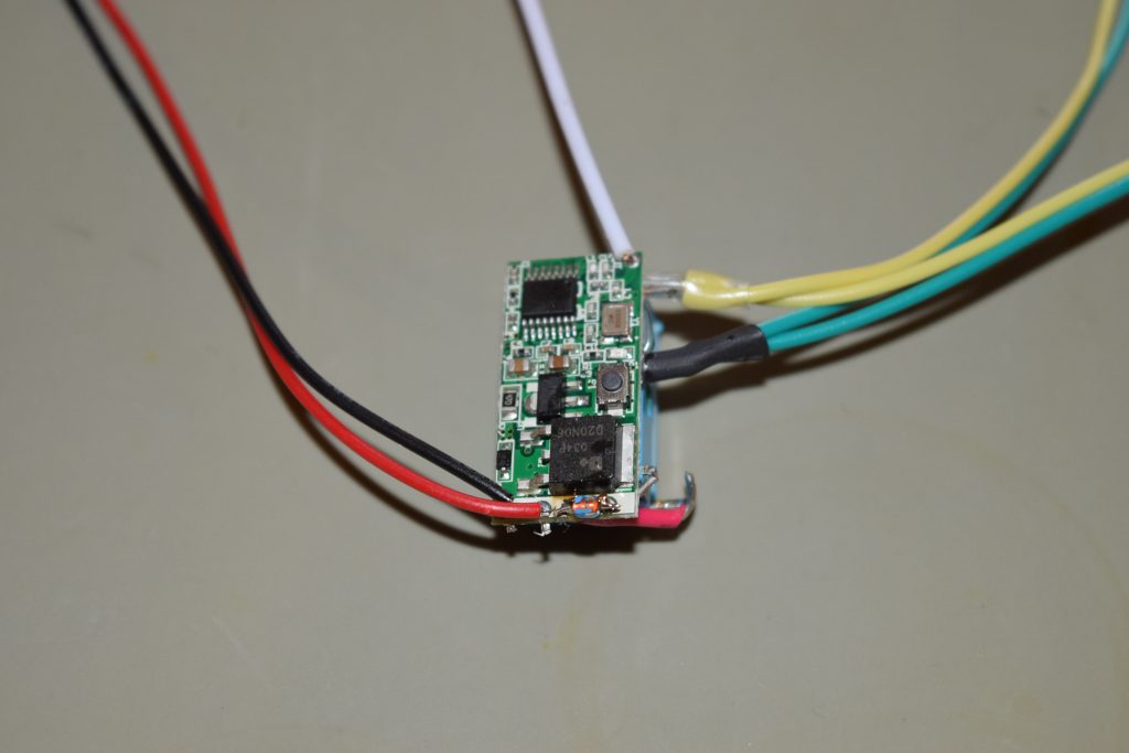
I’d just take a gamble and hook up with a 5V NO relay that I have around. Turned out it actuates with the 5Vsb from the USB header. I glued the relay to the back of the PCB and hook up a flyback/snubber diode (reverse biased) across the relay coil so the back EMF won’t fry my motherboard.
The transmitter switch costs $3.65, which is more expensive than the receiver board. It comes with 12V battery which is typical with 433Mhz door bells.
Press the learning button once and immediately press the transmitter button to pair
Seems like the transmitter-receiver pair is on momentary switch mode by default, so no addition configuration is needed other than pressing the learn button and immediately press the transmitter button to pair.
I wired a jumper extension cable (male – female) to the relay output from the middle as a by-pass since I’d like to keep the original power switch’s functionality (so it’s basically OR-ing between hardwired switch and the wireless remote 433Mhz switch)
The white wire is the antenna
Basic pinouts
Bottom view
Note the reversed-biased diode soldered across OUT+ and OUT- as snubber for relay coil
Close up for construction and the high level wiring.
Here’s an example of taking 5Vsb from USB header and tapping into the power switch jumper in Front-Panel jumper block:
Note that the PWR SW- pin is connected to the ground. Since I’m using a relay, the relay output is floating so the polarity does not matter.
Free Horde Webmail client was ugly so I was looking for alternatives to view my email, calendar, contacts and notes. After a bit of research, I decided to try NextCloud.
NextCloud hosts calendar/tasks (CalDav) and contacts (CardDav) as a server, but do not store emails. Use any email provider (from your ISP or free email services as long as they do IMAP/POP and SMTP).
Default welcome/demo files are under /core/skeleton (you can change this by editing /config/config.php)
If you move the folder, you have to edit the database and root location paths in /config/config.php
Need to setup MySQL first. Avoid PostgreSQL option as it does not work out of the box.
Disable sqlite3 PHP extension
If installed on shared hosting, install without featured app because it will install CODE which is a can or worms.
Collabora Online is a can of worms. See below
Collabora Online (LibreOffice engine to edit documents live on web browsers) require special handling:
There’s a free community edition called CODE (Collabora Online Development Edition)
Do NOT install the BUILT-IN CODE server Nextcloud App if you NextCloud is on a shared hosting because this will appear as a rogue app that slows Nextcloud to a crawl, exhausting entry processes (aka concurrent Apache requests), and still it’ll timeout opening a document. Probably malfunctioning due to some permission issues on shared hosting.
Ports that need to be opened (more accurately port-forwarded to the CODE server) for Collabora:
443 (HTTPS)
Turns out port 80 (HTTP that starts with Univention administration interface) is not necessary. It just redirects to port 443 (HTTPS) if you forgot to type the URL starting with https:// (it’s http:// by default when you type in the address bar of your browser).
Since the URL of Collabora Online-server in NextCloud settings uses only HTTPS and a HTTP URL is going to be redirected to HTTPS anyway, don’t bother with forwarding Port 80 (HTTP) and enter https:// in the Collabora Online-server URL instead.
You don’t need to forward 9980 (WOPI) either. Somebody mentioned it in Nextcloud forum but that’s not the cause.
Well, the next part is the hairiest. Turns out even the Collabora server checks out with NextCloud, the documents won’t open (some weird error messages):
The webpage at https://<Collabora Server>/loleaflet/23e6a73/loleaflet.html?WOPISrc=https%3A%2F%2F<Collabora Server>%2Findex.php%2Fapps%2Frichdocuments%2Fwopi%2Ffiles%2F2180_octqxsu7tnwz&title=<Filename of document to edit>&lang=en&closebutton=1&revisionhistory=1 might be temporarily down or it may have moved permanently to a new web address.

Of course, substitute <Collabora Server> and <Filename of document to edit> with your scenario.
I tried going to https://<Collabora Server> and noticed this NET::ERR_CERT_AUTHORITY_INVALID error:
Turns out given my server do not have the SSL certificate installed yet (and I got around it by “Disable certificate verification” in Collabora Online setup), my users/clients has to manually visit the Collabora (NOT NextCloud) server and click through the security warning to accept the Collabora site that do not have a valid SSL certificate. After that the Collabora Online works properly!
In other words, if you run into certificate issues with Collabora server, NextCloud won’t tell you when it calls Collabora server (with REST API) to open the document, instead it’ll just appear as a fail HTTPS call without warning or giving you a chance to correct the certificate issue.