My sister’s computer is was infected with a bunch of stubborn malware. Even after cleaning the offending files, a lot of things won’t wouldn’t work.
Windows Update, run sfc /scannow, or DISM /Online /Cleanup-Image fails with unknown reasons, which I found it somehow related to “Windows Module Installer” service not running.
I saw something weird in services.msc: “Windows Module Installer” doesn’t exist, but I know the underlying name is “TrustedIntaller” and noticed a service named as such is there, but it cannot be started, nor there are any descriptive information.
So I searched registry for “TrustedInstaller” and got to its entry. I noticed these two:
It means the meaningful names and descriptions I saw on services.msc are generated by calling the underlying service executable file with switches. I checked my “C:\Windows\servicing” and found that “TrustedInstaller.exe” is not there at all! Of course you cannot start a service where the file does not exist at the promised path (ImagePath).
I searched the hard drive and found only one instance of the file stored somewhere (like C:\Windows\winsxs\x86_microsoft-windows-trustedinstaller_31bf3856ad364e35_6.1.7600.16385_none_90e389a7ae7a4b6c) and I tried to move the file to “C:\Windows\servicing”. However the ownership and permissions to write to “C:\Windows\servicing” goes to “TrustedInstaller” account, not “Administrator”, so I took the ownership, gave Administrator full rights, then move the file over.
Everything worked after that! Just the mere trick of deleting TrustedInstaller.exe is enough to make the user miserable trying to clean the system up! “sfc /scannow” or the like requires TrustedInstaller/WIM to be working in the first place, so you cannot use it to repair TrustedInstaller/WIM problems.
Hooking up a floppy drive after a decade of disuse today, I followed the notch/key on the connector/cable but it turns out to be incorrect! Turns out I should do the opposite, forcing the key to the side without the notch, by force (or trim the key)!
So stick with the conventional wisdom that the ribbon’s pin 1 (marked) should always stay close to the power connector, regardless of whether it’s IDE or FDD (3.5″ or 5.25″), EVEN IF FOOLPROOF MECHANISMS TELLS YOU OTHERWISE!
Over the last year, I got a couple of requests for 54616B that specifically ask for a “vertical output” port at the back. I have never seen an oscilloscope that came with such a port, including a few hundred of first generation first generation 54600s I acquired from many different sources.
I got curious and looked it up. Turns out it’s a secondary feature of a relatively obscure option (only mentioned in the manuals, but I have never seen one) called Option 005, which lets you analyze (like count lines) and trigger over common TV signals, like PAL/NTSC/SECAM, which is way obsolete today. It also seems that none of the customers asking specifically for the “vertical output” port at the back know that it is a super rare option that is normally not included, so they must be using it for something else other than analog TV signal analysis.
A closer look at the user guide shows that “vertical output” port duplicates the signal source (e.g. channel 1) that the scope is triggering on, limited to what is seen by the oscilloscope, to the said “vertical output” port, a secondary feature to let you chain your signal to instruments like spectrum analyzers for further analysis.
I tried the feature myself by chaining the output to another oscilloscope. Even if the waveform is off-screen for the current vertical volts/div, the vertical output port waveform did not clip. I also played around with input impedance settings 1MΩ and 50Ω for a 50Mhz square wave. Based on what gets the square wave badly distorted, I can confirm that the vertical output signal is the analog signal after attenuator (the amplitude changes only with Volts/div that causes relay clicks) but before ADC, assuming a 50Ω load.
Wait! An oscilloscope that duplicates the input analog signals after being processed by the front end (post-attenuator, pre-ADC) to an external output port?! I don’t have to mess with the original signal path by splitting the signal (passively) or make an amplifier to duplicate the signal? Wow! How come it’s not standard (or at least a purchasable option) in modern oscilloscopes? I’d like to see what’s going on with the analog waveform before the scope processes it! Not only it’s very educational, it allows other instruments to get an accurate insight of what the oscilloscope is seeing. Neat!
Installing the Option 005 is not difficult if you happen to have an unobtainium Option 005 case with labels, and the entire kit with all the necessary interconnect. However, it’s like an unicorn and I’ve never seen one. Drilling professional looking holes for it is a nightmare as we don’t have the dimensions. The hardware is also insanely hard to get as it was made for a specialized crowd for the time and practically nobody cared about analog TV signals nowadays. Even if I can get that, they are most often missing the interconnects. The ribbon cable is missing for nearly all of them, and if you get a standard ribbon cable, you’ll realize the plastic retainer gets into the way of a screw on the main acquisition board so the Option 005 card won’t slide in unless you trim some of the plastic off. PITA!
Nowadays I am already spoiled by high end gears like MSO6054A and 13Ghz Infiniiums (like DSO81304A), but none of them has a convenient analog, post-attenuator output like a first generation 54600 with an Option 005. Given the hardware is scarce, I’ll save it for the top of the line first generation 54600 series, namely 54616B and 54616C.
For those who have this special need (need to tap into the pre-ADC signals up to 500Mhz), I can custom build these Option 005 units for you, depending on parts availability. Call me at 949-682-8145 or reach me at my business website www.humgar.com.
Complex conversions between decibels and physical quantity has always been a rich source of confusion. The reason is that dB(something) is actually a loaded word with hidden assumptions:
dB always works on base-10
dB is always a relative (dimensionless) POWER quantity.
The POWER quantity can be expressed in terms of non-power quantities (like voltages).
the scaling factor is always 10 for power.
Adding one zero (multiply by 10) to the power ratio means +10dB.
dB(something) is always with respect to a quantity (the something), and the reference quantity is often not written in full. Since there is an implicit reference, db(something) can be mapped to absolute quantities.
If you are a diverse multi-disciplinary techie like me (math, electronics, programming, computers), it’d frustrate the hell out of you when you talk to people who has been working exclusively on a narrow field for at least a decade and they have a table of commonly used numbers in their memorized: they act like you are supposed to know how to get the numbers in the dB-variant that they use, than explaining to you what the field-specific assumptions are (likely because they forgot about it).
I hope this post will clear up the confusion by working out an example in test instrumentation, most commonly in RF as well, converting dBm to Volts.
Before I start, I’ll clarify the most common form of beginner confusion in EE and physics: converting between dB and voltages:
This looks like a definition of decibel, except the scaling factor is 20 magically for Volts. It is correct because we always work in power and power can be expressed as voltage-squared (resistances in the divisor cancel out if they are the same). Most people take it as an equivalent definition of decibels, and throw away these important assumptions behind it:
the reference is 1V,
and the resistance* (common to the voltage of interest and the reference voltage) gets cancelled
and run into troubles when they venture into those dB-variants like dBm. Technically the above should be written as dBV, but I have seen very few people use the clearer term.
The decibel formula for voltage came from
where and , you get
The get cancelled out and you get
People moved the squaring out and lumped (multiplied) it with the scaling factor 10:
So the whole reason why it is instead of is simply because , and .
Now back to the business converting dBm to dBV or Volts.
First of all dBm is dB(mW), NOT dB(mV). The RF/telecom people are just too lazy to write out the most important part: the physical quantity expressly, because nearly all the time, it’s the power that matters to them.
However, I often need to connect a RF generator to a high bandwidth oscilloscope, so the very self-centered RF/telecom nomenclature start to become problematic when people of different fields need to talk to each other. Oscilloscope see everything in volts. RF sees everything in power, often in dB.
Then we get to the (mW) part, which means the reference quantity in the definition is 1mW, which is a physical quantity with dimensions. Then how are we going to convert it to Volts? You cannot jump to the shortcut formula I illustrated above with the 20 factor this time because the reference is in mW and your quantity is in Volts.
You’ll need to convert power to voltages. To do so, you’ll need to know voltages induced by power ‘dissipated’ through a ‘resistance’ across a component (load). The missing gap is that you will need to know the load ‘resistance’ before the conversion. With that, you can use , or rewritten as when it’s more convenient.
All RF-related test-instruments and bench function generators typically have a 50Ω output impedance, which means it also assumes a matching 50Ω as mathematically, it provides the maximum power transfer (sadly split evenly between the load and wasted at the instrument’s output impedance). For convenience, the amplitude you see in the instrument control panel refers to the amplitude you see at a 50Ω load, not what the instrument pumps out internally (that’s why you see 2Vpp when your function generator says 1Vpp if you hook it up to a low-end oscilloscope that serves 1MΩ by default).
Since we are dealing with continuous wave (not transient power), all amplitude quantities on RF test instruments are in RMS (power or voltage) unless otherwise specified. So the quantities we have for dBm is
when written in terms of voltages,
Instead of splitting it into 3 terms and immediately grouping the constants, I’d like to first convert dBm to dBW:
The linear quantity in dBm is artificially scaled 1000 times bigger than in dbW, to put it in a comfortable scale for us to work with smaller signals. Therefore dBm is always 30dB higher than dbW (the smaller the reference, the bigger the relative numbers look).
So back to the above in dBW, we subtract 30dB to get to dBW:
where
We can separate the load and put it on the left hand side
The right hand side is dBV, and you can think of the load as scaling the power up (inducing) the voltage-squared quantity (, or ).
is 16.9897dB, for most purposes I’ll just say the load lift the dBW by 17dB when turning it into dBV.
Having both together,
(This is how you should remember it, so you can replace the +17dB for 50Ω with when you work on other applications, like 600Ω, 4Ω, 8Ω for audio.)
Basically:
-30dBto undo the mili- prefix at reference power (with dBm, the power ratio is bloated by 1000 times, aka by 3 zeros) +17dBto account for the load inducing the voltage by burning Watts
The end result (for the 50Ω case):
Then you can convert dBV to :
Phew! That’s a lot of steps to get to something this simple. So the moral of the story is that these assumptions cannot be ignored:
The quantity is always power in dB, not voltages
dB(mW) has a reference of 1mW. The smaller the reference, the bigger the numbers
RMS voltages and power are used in RF
50Ω is the load required to convert from power to voltages
Keysight already has a derivation, but it’s just a bunch of equations. The missing gap I want to fill in this blog post is that people find this so confusing they’d rather believe a formula or a table pulled on the internet: it doesn’t have to be this way after realizing that there’s a bunch of overlooked assumptions.
* Technically I should call it (load) impedance , as in RF, capacitive and inductive elements are nearly always involved, but I want to make it appealing to those with high school physics background.
While servicing a TDS 754A for a client, I smelled burnt electrolyte near the power supply section. Although it isn’t the cause of the problem yet, I know it’s a ticking time bomb.
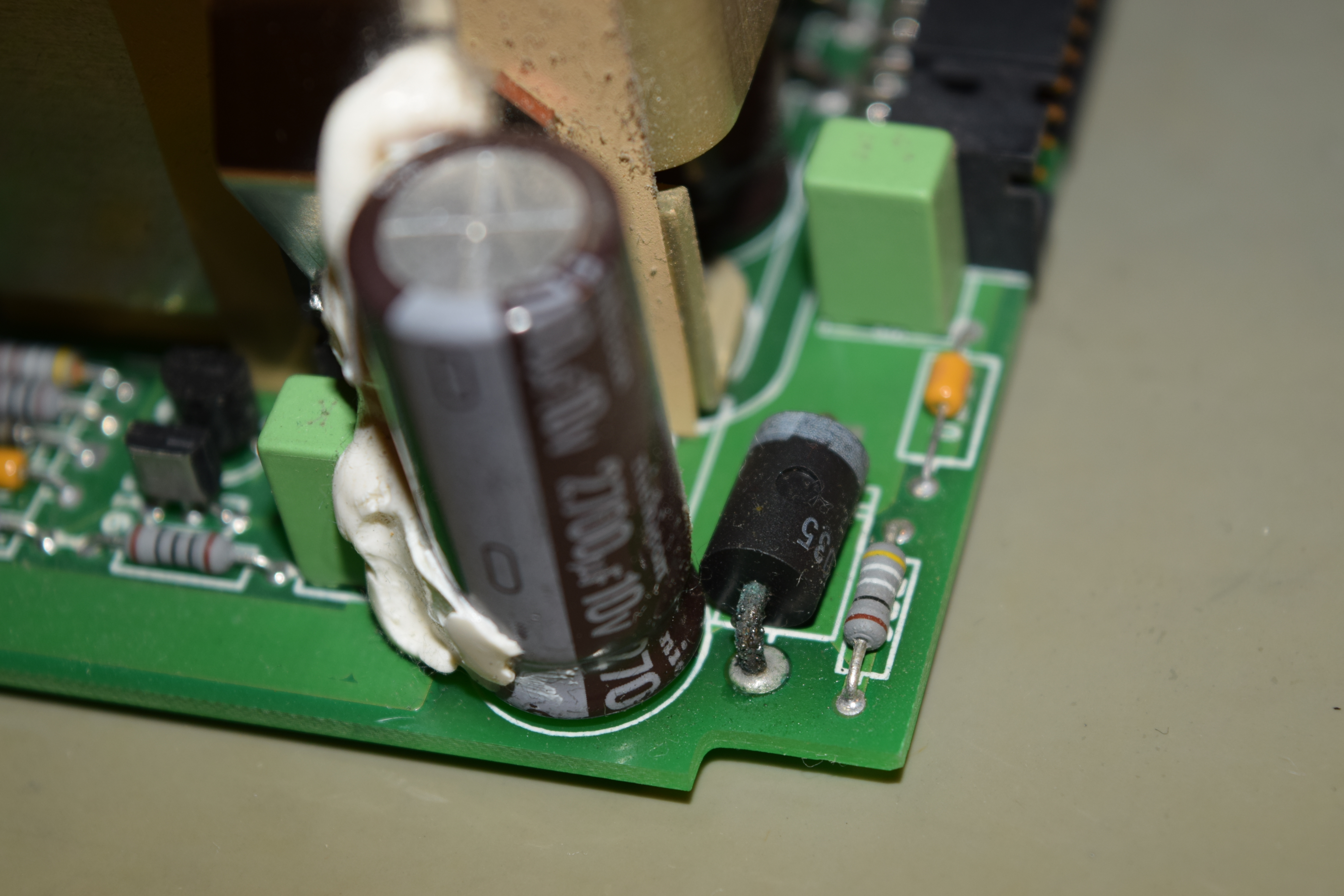
By comparing the good power supply from my TDS 784A (same base design), I saw one of the leads of a higher power diode looks corroded (black stuff) yet the same diode on the good power supply has rainbow discoloration. It suggested that the assembly of the same part number is likely to fail by poor design (must be heating too close to the capacitor). Here’s the comparison of the C49 that caught my attention:
TDS 754A (Bad for sure)
TDS 784A (Slightly better. Less obvious leak)
And after removing C49 on TDS 754A, it’s clearly this capacitor has leaked and corroded one of the diode’s lead nearby:
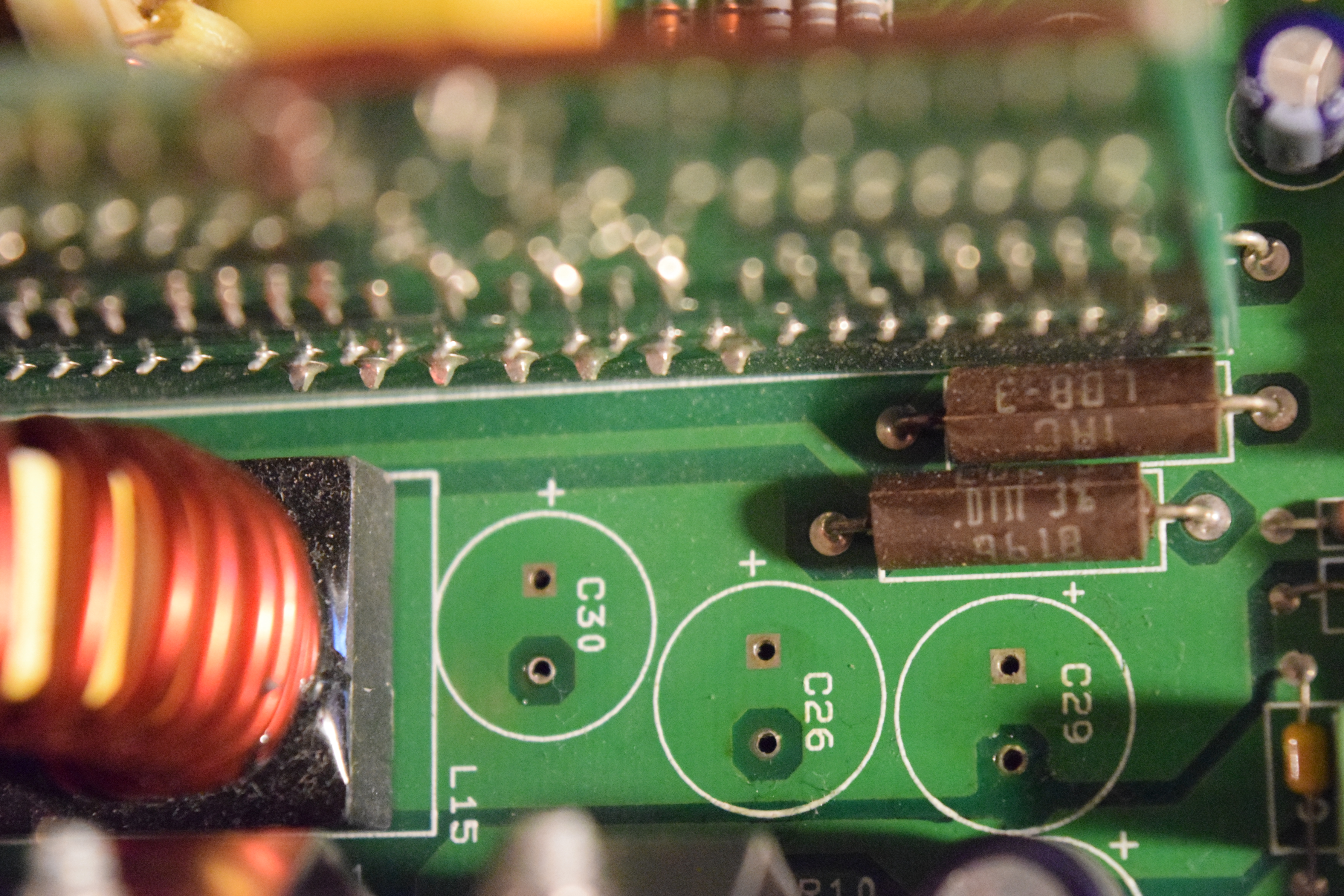
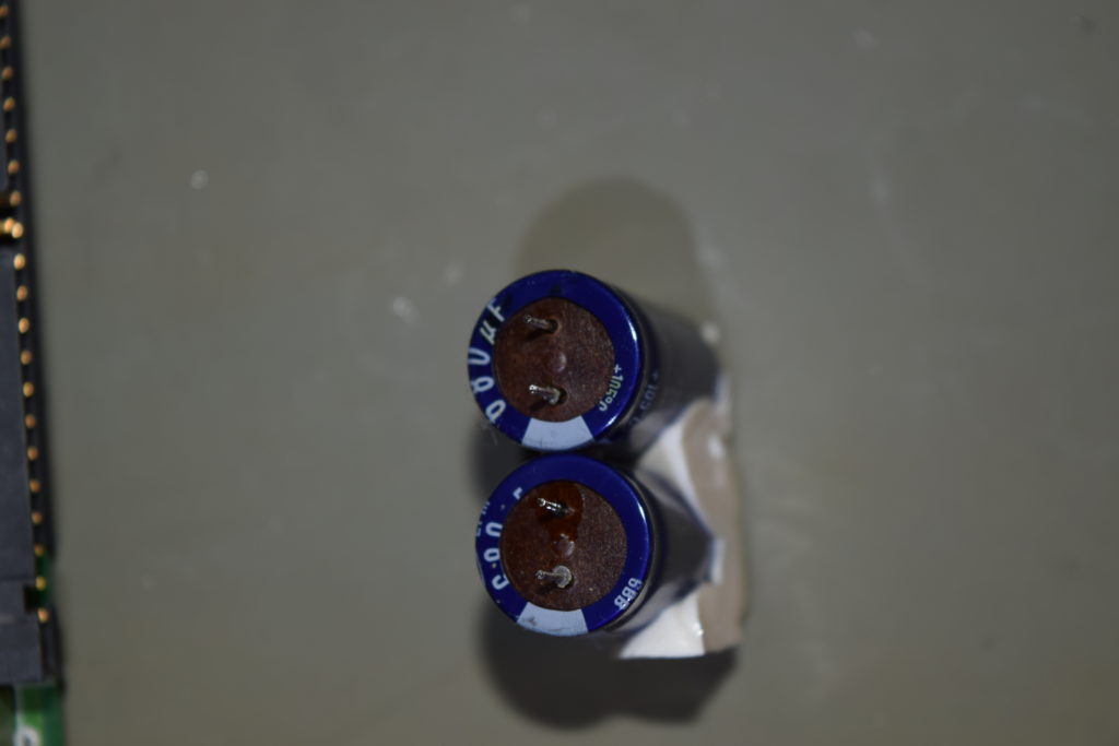
By taking a closer look, I noticed a bit of stains around most 2700uF 10V Nichicon capacitors. Only C86 and C30 haven’t leaked yet. Might as well replace them all since there are 8 of them and 6 of them leaked.
C85 has green stuff all over it and smelled horrible. Surprisingly the ESR and capacitance is still within specs. That’s why the unit still functions. It’s just a matter of time before the power supply blows up and take out the commonly known transistors with it if I had left it there:
C47 and C48 is a mess:
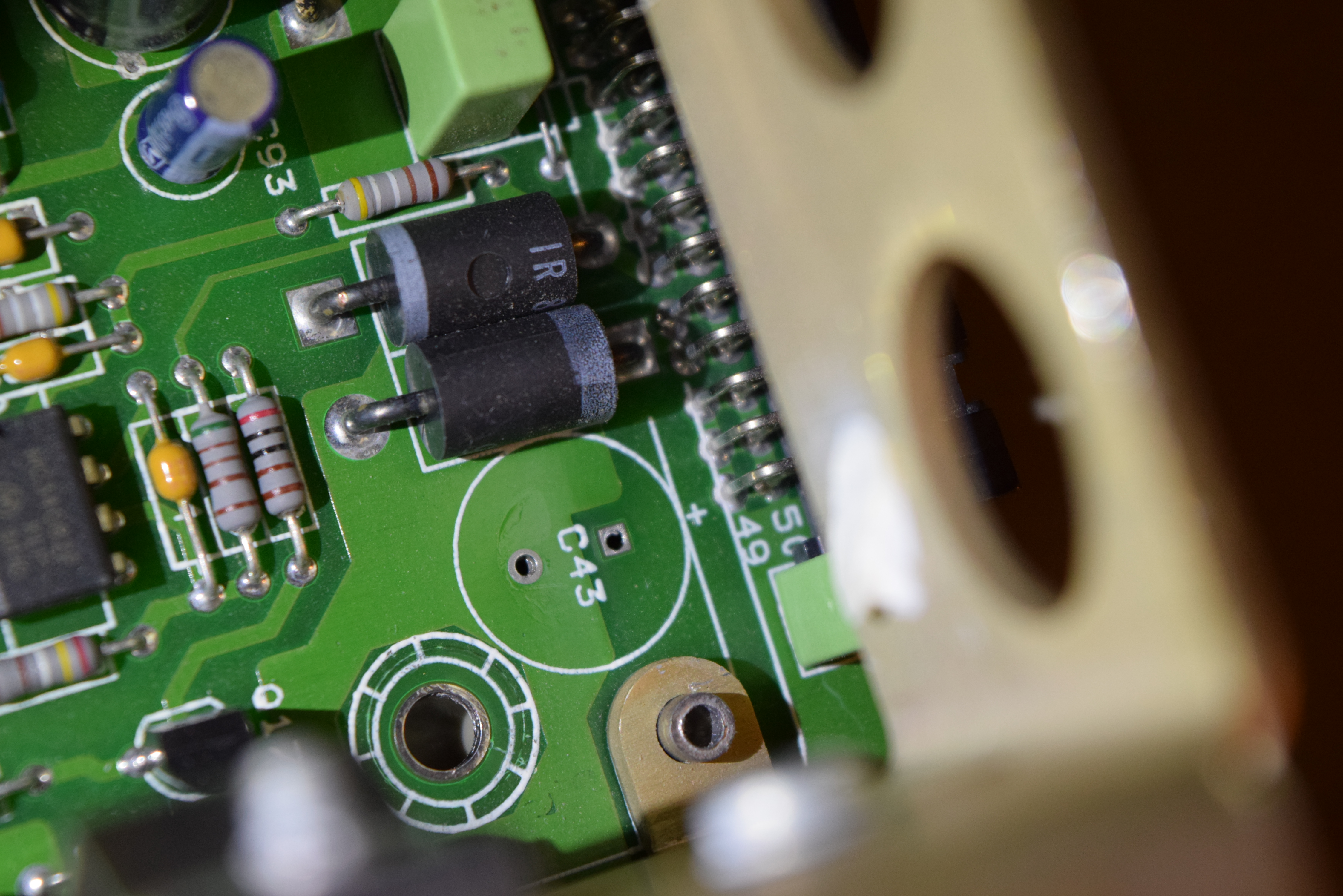
C43 doesn’t look too bad, but it actually leaked. The clear fluid there is not flux, and the diode leads nearby stained for a reason:
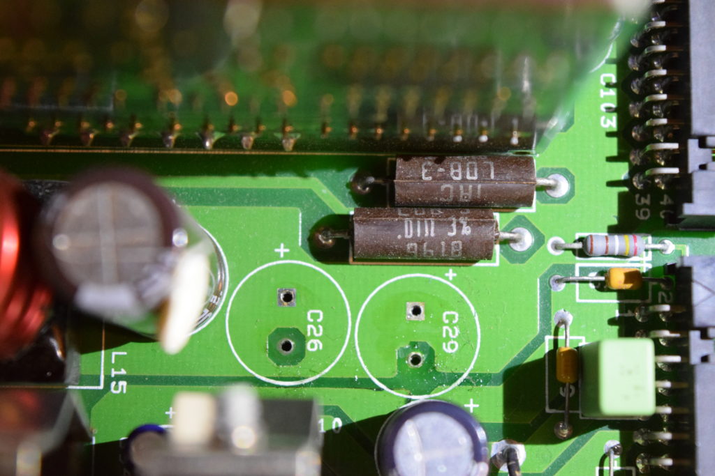
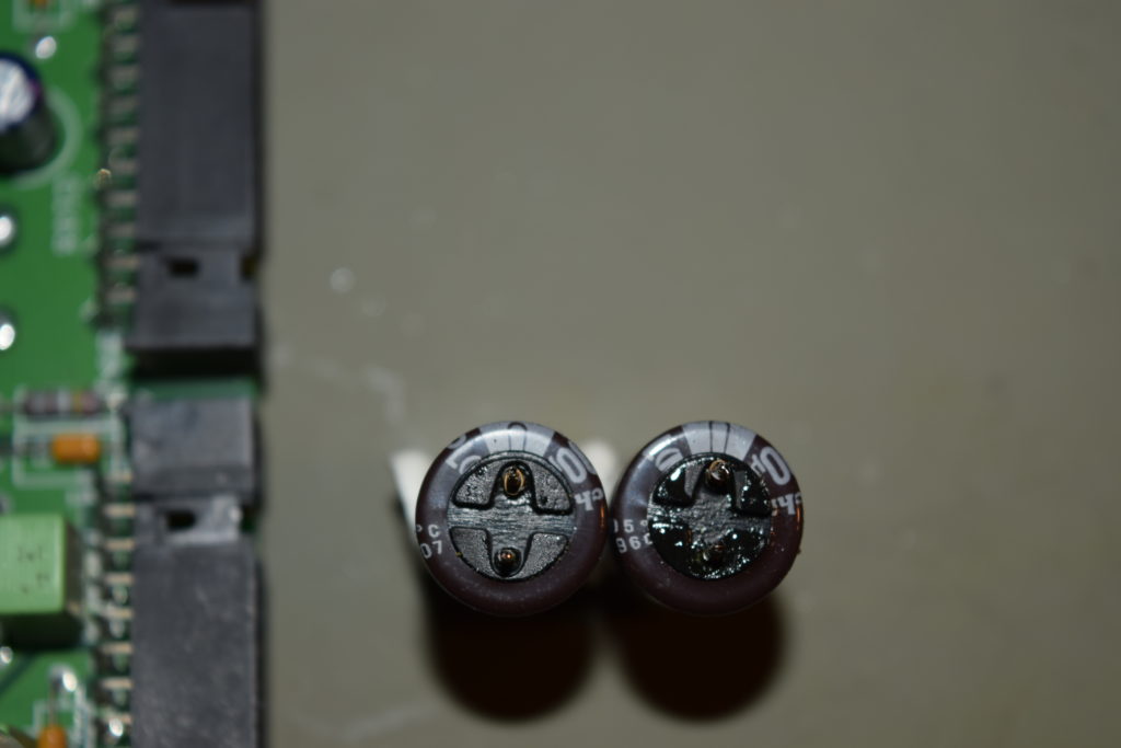
C29 and C26 leaked as well:
C29 C26 leak PCB
C29 C26 leak Caps
C30 near them is clean though, the one out of two survivors:
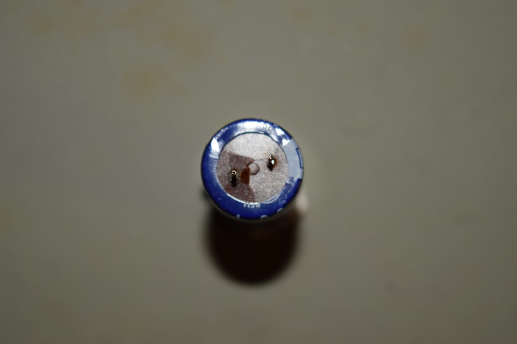
Despite I haven’t seen leak residue on the PCB for the 680uF 35V, they are located close to high heat areas so I desoldered them to take a look. Turns out C21 cracked,
C21
C21 Cracked
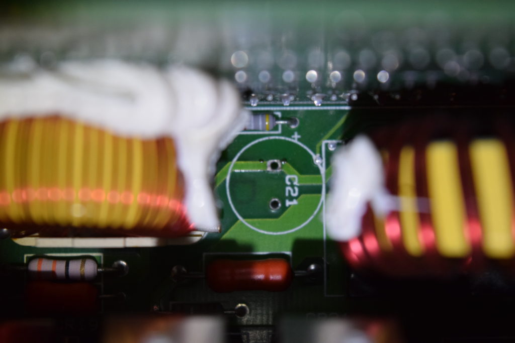
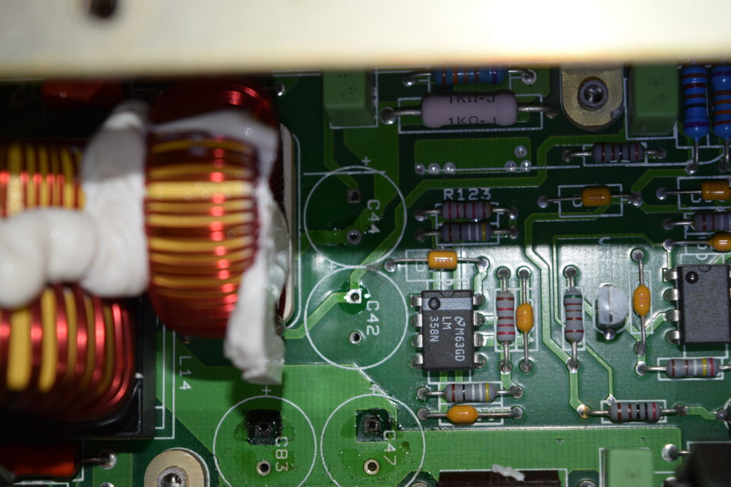
C44 leaked a little, C42 is intact (it’s just flux):
C44 (Top) C42 (Bottom)
C44 (Top) C42 (Bottom)
All 680uF there are Marron capacitors.
So basically, I couldn’t trust the caps anymore and I desoldered the rest to check for leaks. Some of the Matsushita / Panasonic branded tinier capacitors far from heat sources survived. The 100uF 25V capacitor (Matsushita) at C33 near the heatsink also leaked, but it’s not too visible until I see the corroded pads after desoldering it.
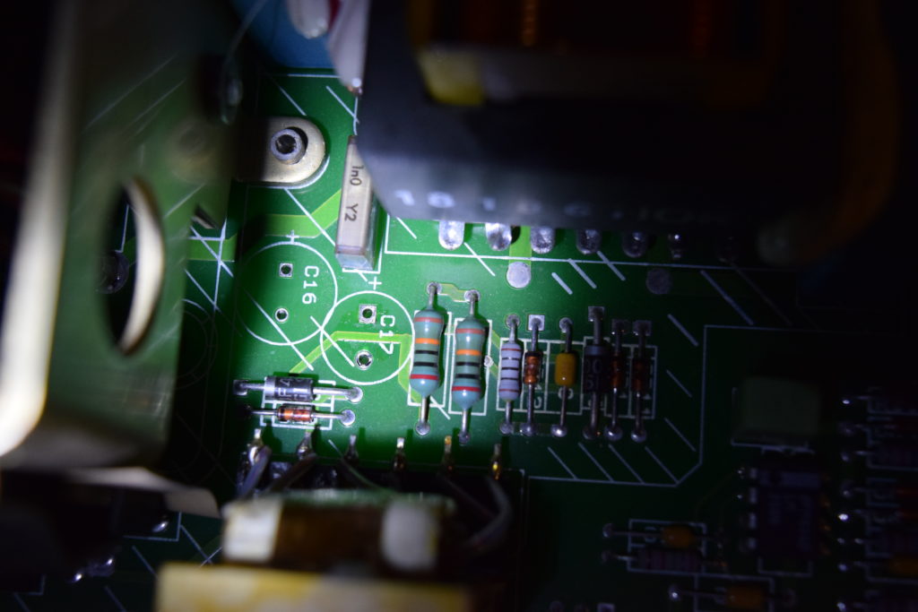
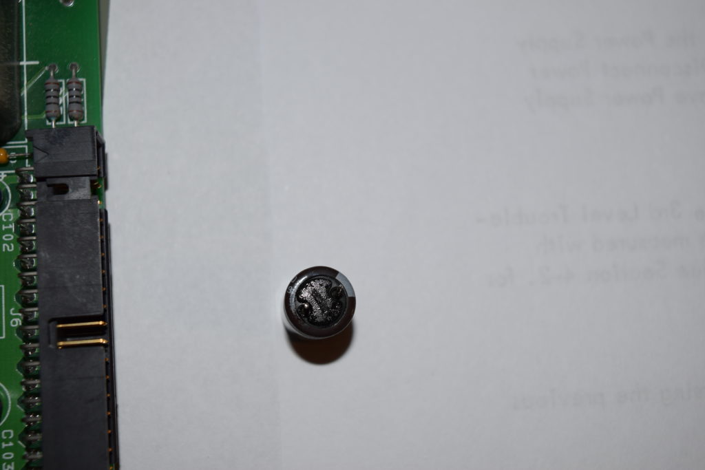
I took out the last Nichicon there, a smaller 47uF 80V at C17, despite I don’t see any visible leaks before I desolder it. Glad that I did. It clearly leaked (can see it by looking at the bottom of the extracted capacitor), but not outside the capacitor’s casing’s diameter:
C14 Leak PCB
C14 Leak Capacitor
To avoid troubleshooting nightmare (uncommon problems) in the future, replace ALL electrolytics on the power board regardless of whether they are good or not given the majority of the capacitors leaked in this example. If you leave one or two old capacitors there and they leaked in the future, it’d be an uncommon problem that you can’t get any advice anywhere since nobody serviced the unit the same way as you did.
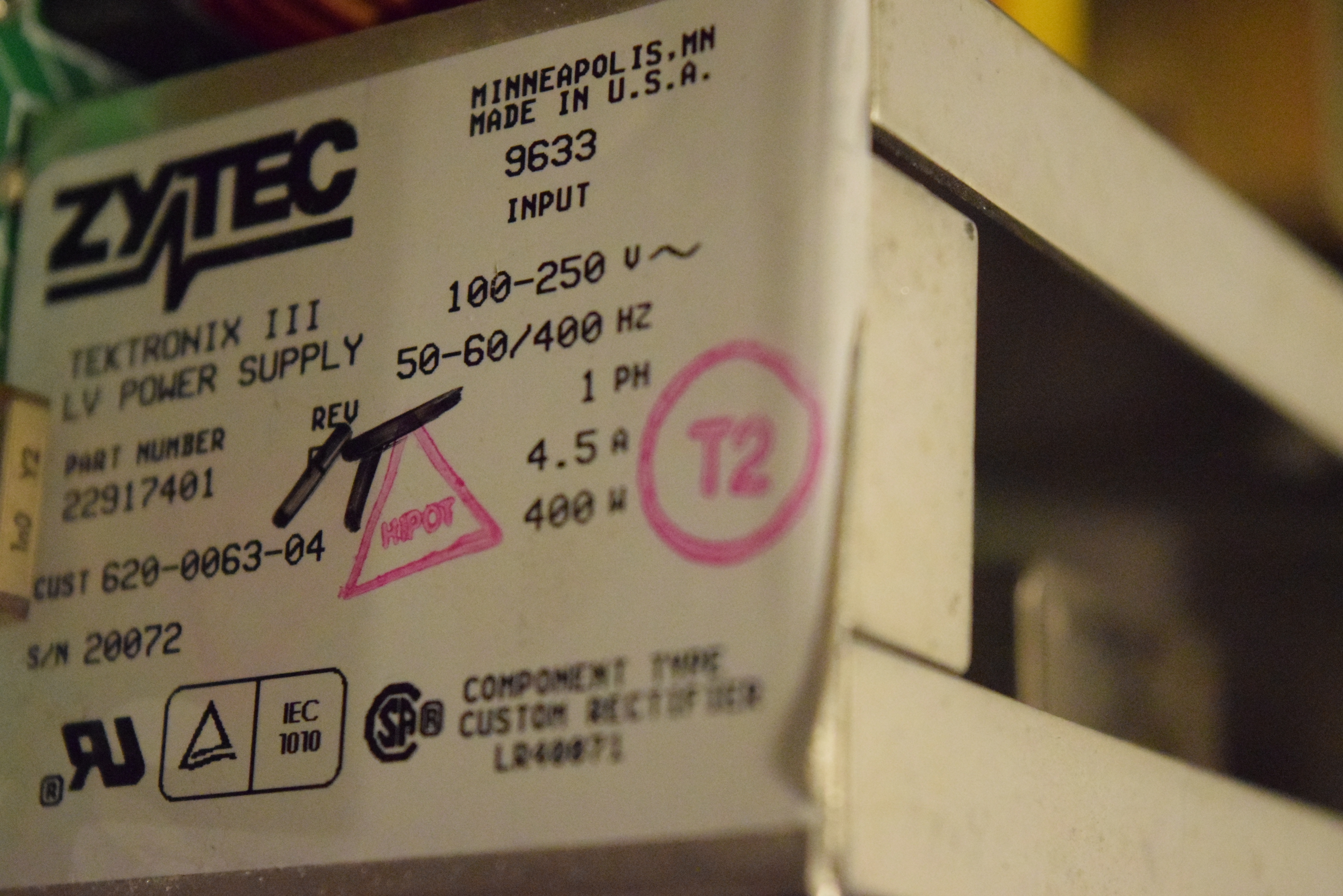
To be fair, Tektronix didn’t make this 400W power supply, Zytec did:
I used to think that the TDS 700 series doesn’t need much work because the SMD aluminum electrolytic capacitors on the acquisition board. But now I can see that anything that’s electrolytic leaks (CRT driver, power supplies, front-panel keypad, RS-232/Centronics board, processor board) in this TDS 500~700 series.
Nonetheless, it’s still a positive trait that there are no electrolytics on the TDS 700 series acquisition board, as it’s the most expensive and fragile piece. Acquisition board with leaked electrolytes is toasted (beyond economic repair) if you leave the electrolyte there too long.
Do NOT buy TDS 300~800 series off used market if you do not have to (like you have automation written for it or you’ve used it for 20 years and it’s all ingrained in your head) no matter how cheap they are (or SEEMINGLY working). The money is much better spent on HP 54520/54540 series if you are on a very tight budget. TDS 300~700 series don’t have much usable life left unless it’s verified new-old-stock. All fixes to TDS 300~700 problems are are laborious, frustrating and expensive.
It’s the same things that breaks for the same reason (unreliable design). That means if you simply swap modules with another used unit, or buy another identical unit, you are going to run into problems one way or the other in a short amount of time. Basically, you are only squeezing the last few puffs off a disposed cigarette butt.
I have built the knowledge and parts to rebuild these congenitally sick puppies, but as I discovered the number of common problems are still growing strong, I’m staying out of the market for it and sell whatever I have left (I’ll strengthen them before selling, of course).
If you absolutely have to rebuild a TDS 300~800 series oscilloscope and are willing to spend good money on it, which is typically the case if you:
have an automated system written for it that you need an exact replacement
have used the unit for 20+ years that you’d willing to pay to not painfully relearn.
do not want to change the procedures in a bureaucratic environment
I have the parts and knowledge to extend the unit’s life that you cannot find anywhere else. It’s super involved, but I’d be willing to help if I’m the last resort.
If you choose to send me a unit for rebuild to extend its life, I’ll make it mandatory to replace electrolytics capacitors in these boards:
Processor board
RS-232/Centronics board (Option 2C)
Front panel keypad
CRT driver board
Power supply module
Acquisition board (if your model uses SMD aluminum electrolytics).
Acquisition board cost a lot more to recap as there’s a lot of capacitors if the model uses any.
because electrolytic capacitor failures cause symptoms that are very hard to troubleshoot (most of those are power rail capacitors, which if they fail, unstable voltages gives unpredictable erratic behavior).
The following is optional and billed separately:
New CRT tube for color CRT screens. I have six units left so far. First come, first served.
Tuning the tube to match the CRT board is very labor intensive.
Rebuild attenuator hybrid (they are consumables)
Troubleshoot/repair existing known symptoms
I give 3 years warranty for the repairs or preventative service I’ve carried out and it’s not user inflicted damage after the repair (like feeding high voltage to the inputs).
Call me at 949-682-8145 if you are truly need to rebuild a TDS 500~700 model and is willing to pay good money for it.


 and
and  , you get
 get cancelled out and you get

 instead of
  is simply because
  , and
, and  .
. , or rewritten as
  when it’s more convenient.


 ).
). is 16.9897dB, for most purposes I’ll just say the load lift the dBW by 17dB when turning it into dBV.


 when you work on other applications, like 600Ω, 4Ω, 8Ω for audio.)
 :
:


 , as in RF, capacitive and inductive elements are nearly always involved, but I want to make it appealing to those with high school physics background.