GPIB to Ethernet Gateway (Agilent E2050A or E5810A, NI, Tek, ICS) Don't bother with USB-GPIB adapters. Ethernet-GPIB gateways are cheaper and better.

GPIB gateway is a device that allows you to remotely control / talk-to test instruments (as well as ancient printers/plotters, etc) that uses the most popular protocol. It’s so popular and timeless that even new test instrument finds a way to support it. This protocol just wouldn’t die.

The major downside of USB-GPIB interfaces (cheaper) is that it requires driver support, which is OS dependent. Keysight can choose to drop support at anytime. You can always fire up a virtual machine to use old software talking to a hardware using TCP/IP, but not reliably with USB (sometimes you get glitches and timing issues with virtual machines especially when it streams live data even at kHz range).

It’s usually a good idea to stick with GPIB if you have an automation setup that involves at least ONE piece of test instrument on GPIB. A ethernet port (LXI) on a modern test gear is fine, but you don’t really want to complicate your code managing network connectivity checks for each IP-based instrument and make sure they work together. With GPIB, you can chain 14 instruments with one gateway so you don’t have to worry about network problems if you can connect to any one of the device on the chain.

Here’s a nice GPIB tutorial document if you’d like to get into the nitty-gritty:
http://www.essproducts.com/wp-content/uploads/2015/06/ab48_11.pdf


E2050A is my favorite GPIB gateway due to its compact size. It’s good enough for most purposes, since I don’t really have any instruments that need or support the extra speed from 488.2. The biggest annoyance is that E2050A does not have DHCP, but uses an an ancient BOOTP instead. This means for modern networks, you might as well give it a static IP.

E5810A is the newer revision of E2050A, with the same internal interfaces. That means all software, including Agilent I/O Suite, fully supports E2050A as a E5810A. E5810A comes with a few minor improvements

  • it adds a web interface (not very useful other than upgrading firmware)
  • supports 488.2, which means 9x faster GPIB communication if the instrument supports it
  • DHCP: automatically acquiring IP address

Unfortunately, E5810A is a bigger unit, partly because the power supply is built-in, and it comes with a LCD screen. Nonetheless, I opened up a E5810A and the inside has a lot of empty spaces.

Telnet is supported for both E5810A and E2050A. For E2050A, telnet is the only way you can get inside the unit and change the configuration such as IP address and interface name. Telnet is pretty easy to use, just get the free, open-source Putty if your Windows does not come with command line telnet anymore.


There’s a E5810B, but in my opinion, it’s pointless because all it adds is a USB-over-IP interface and a front switch. This is something most ASUS routers (especially Merlin firmware) has it out of the box or there are some cheap old USB-over-IP modules (<$50) for it.  Basically if you are considering a E2050/E5810, your eyes are on the GPIB instrument base, not the USB instruments that you can put on the network with low cost USB-over-IP. It’s just fluff for Agilent/Keysight to discontinue support for the earlier models to price differentiate from the units circulating in the used market.


I’ve tried other gateways such as NI and Tektronix. There are not many NI gateways floating around and I’ve only encountered even fewer Tek gateways. Unless you have poorly written software that hard-codes to NI or Tek stack, I wouldn’t even bother installing NI/Tek GPIB stack as it can confuse some poorly designed software if the 3 stacks are not configured properly to work together peacefully. Just stick with the GPIB stack from the brand that you can easily get used units for cheap.

Be very careful about NI GPIB-ENET: it does not support anything after Windows XP at all, and there’s no way NI will bother to go back and fix it. For this I wouldn’t even want to touch any GPIB gateways done by NI since they are not as thoughtful about backward compatibility compared to HP/Agilent/Keysight.

ICS was popular a while ago making cheap GPIB controllers/converters. However, they don’t work with Agilent’s I/O suite or NI/Tek stack directly, so you are stuck with using it like a serial port. Given that the price of a used HP/Agilent’s GPIB gateway is cheaper than a new ICS gizmo, there’s no point getting ICS stuff anymore.


I have E2050A as well as E5810A for sale. Please contact me from my business website (www.humgar.com) or my phone 949-682-8145.

Loading

The mess converting decibels to voltages in test instruments (dBm, dBW, W, dbV, V)

Complex conversions between decibels and physical quantity has always been a rich source of confusion. The reason is that dB(something) is actually a loaded word with hidden assumptions:

  • dB always works on base-10
  • dB is always a relative (dimensionless) POWER quantity.
    The POWER quantity can be expressed in terms of non-power quantities (like voltages).
  • the scaling factor is always 10 for power.
    Adding one zero (multiply by 10) to the power ratio means +10dB.
  • dB(something) is always with respect to a quantity (the something), and the reference quantity is often not written in full. Since there is an implicit reference, db(something) can be mapped to absolute quantities.

If you are a diverse multi-disciplinary techie like me (math, electronics, programming, computers), it’d frustrate the hell out of you when you talk to people who has been working exclusively on a narrow field for at least a decade and they have a table of commonly used numbers in their memorized: they act like you are supposed to know how to get the numbers in the dB-variant that they use, than explaining to you what the field-specific assumptions are (likely because they forgot about it).

I hope this post will clear up the confusion by working out an example in test instrumentation, most commonly in RF as well, converting dBm to Volts.


Before I start, I’ll clarify the most common form of beginner confusion in EE and physics: converting between dB and voltages:

\mathrm{dB} = 20\log_{10}(V) = 10\log_{10}(V^2)

This looks like a definition of decibel, except the scaling factor is 20 magically for Volts. It is correct because we always work in power and power can be expressed as voltage-squared (resistances in the divisor cancel out if they are the same). Most people take it as an equivalent definition of decibels, and throw away these important assumptions behind it:

  • the reference is 1V,
  • and the resistance* (common to the voltage of interest and the reference voltage) gets cancelled

and run into troubles when they venture into those dB-variants like dBm. Technically the above should be written as dBV, but I have seen very few people use the clearer term.

The decibel formula for voltage came from

\mathrm{dBV} = 10\log_{10}(\frac{P}{P_{ref}})

where P = \frac{V^2}{R} and P_{ref} = \frac{1^2}{R}, you get

\mathrm{dBV} = 10\log_{10}(\frac{V^2/R}{1^2/R})

The R get cancelled out and you get

\mathrm{dBV} = 10\log_{10}(V^2)

People moved the squaring out and lumped (multiplied) it with the scaling factor 10:

\mathrm{dBV} = 20\log_{10}(V)

So the whole reason why it is 20 instead of 10 is simply because P\propto V^2, and \log(V^2) \equiv 2\log(V).


Now back to the business converting dBm to dBV or Volts.

First of all dBm is dB(mW), NOT dB(mV). The RF/telecom people are just too lazy to write out the most important part: the physical quantity expressly, because nearly all the time, it’s the power that matters to them.

However, I often need to connect a RF generator to a high bandwidth oscilloscope, so the very self-centered RF/telecom nomenclature start to become problematic when people of different fields need to talk to each other. Oscilloscope see everything in volts. RF sees everything in power, often in dB.

Then we get to the (mW) part, which means the reference quantity in the definition is 1mW, which is a physical quantity with dimensions. Then how are we going to convert it to Volts? You cannot jump to the shortcut formula I illustrated above with the 20 factor this time because the reference is in mW and your quantity is in Volts.

You’ll need to convert power to voltages. To do so, you’ll need to know voltages induced by power ‘dissipated’ through a ‘resistance’ across a component (load). The missing gap is that you will need to know the load ‘resistance’ before the conversion. With that, you can use P = V^2/R, or rewritten as V^2 = PR when it’s more convenient.

All RF-related test-instruments and bench function generators typically have a 50Ω output impedance, which means it also assumes a matching 50Ω as mathematically, it provides the maximum power transfer (sadly split evenly between the load and wasted at the instrument’s output impedance). For convenience, the amplitude you see in the instrument control panel refers to the amplitude you see at a 50Ω load, not what the instrument pumps out internally (that’s why you see 2Vpp when your function generator says 1Vpp if you hook it up to a low-end oscilloscope that serves 1MΩ by default).

Since we are dealing with continuous wave (not transient power), all amplitude quantities on RF test instruments are in RMS (power or voltage) unless otherwise specified. So the quantities we have for dBm is

\mathrm{dBm} = 10\log_{10}(\frac{P_{rms}}{1mW})

when written in terms of voltages,

\mathrm{dBm} = 10\log_{10}(\frac{V^{2}_{rms}/50Ω}{1mW})

Instead of splitting it into 3 terms and immediately grouping the constants, I’d like to first convert dBm to dBW:

\mathrm{dBW} = 10\log_{10}(P/1W)

\mathrm{dBm} = 10\log_{10}(P/0.001W) = 10(\log_{10}(P/1W) + \log_{10}(1000))

The linear quantity in dBm is artificially scaled 1000 times bigger than in dbW, to put it in a comfortable scale for us to work with smaller signals. Therefore dBm is always 30dB higher than dbW (the smaller the reference, the bigger the relative numbers look).

So back to the above in dBW, we subtract 30dB to get to dBW:

\mathrm{dBm} = \mathrm{dBW} + 30\mathrm{dB}

where

\mathrm{dBW} = 10\log_{10}(V^{2}_{rms}/50Ω)

We can separate the load and put it on the left hand side

\mathrm{dBW} + 10\log_{10}(50Ω) = 10\log_{10}(V^{2}_{rms})

The right hand side is dBV, and you can think of the load as scaling the power up (inducing) the voltage-squared quantity (V^2 = PR, or \log(V^2) = \log(P) + \log(R)).

10\log_{10}(50Ω) is 16.9897dB, for most purposes I’ll just say the load lift the dBW by 17dB when turning it into dBV.

Having both together,

\mathrm{dBW} + 17\mathrm{dB} = \mathrm{dBV}
\mathrm{dBW} = \mathrm{dBm} - 30\mathrm{dB}

\mathrm{dBm} - 30\mathrm{dB} + 17\mathrm{dB} = \mathrm{dBV}
(This is how you should remember it, so you can replace the +17dB for 50Ω with
10\log_{10}(R) when you work on other applications, like 600Ω, 4Ω, 8Ω for audio.)

Basically:

-30dB to undo the mili- prefix at reference power
(with dBm, the power ratio is bloated by 1000 times, aka by 3 zeros)
+17dB to account for the load inducing the voltage by burning Watts

The end result (for the 50Ω case):

\mathrm{dBV} = \mathrm{dBm} - 13\mathrm{dB}

Then you can convert dBV to V_{rms}:

\mathrm{dBV} = 10\log_{10}(V^2_{rms}/1^2) = 20\log_{10}(V_{rms})

V_{rms} = 10^{\frac{\mathrm{dBV}}{20}}

V_{rms} = 10^{\frac{\mathrm{dBm}-13dB}{20}}

Phew! That’s a lot of steps to get to something this simple. So the moral of the story is that these assumptions cannot be ignored:

  • The quantity is always power in dB, not voltages
  • dB(mW) has a reference of 1mW. The smaller the reference, the bigger the numbers
  • RMS voltages and power are used in RF
  • 50Ω is the load required to convert from power to voltages

Keysight already has a derivation, but it’s just a bunch of equations. The missing gap I want to fill in this blog post is that people find this so confusing they’d rather believe a formula or a table pulled on the internet:  it doesn’t have to be this way after realizing that there’s a bunch of overlooked assumptions.


* Technically I should call it (load) impedance Z, as in RF, capacitive and inductive elements are nearly always involved, but I want to make it appealing to those with high school physics background.

Loading

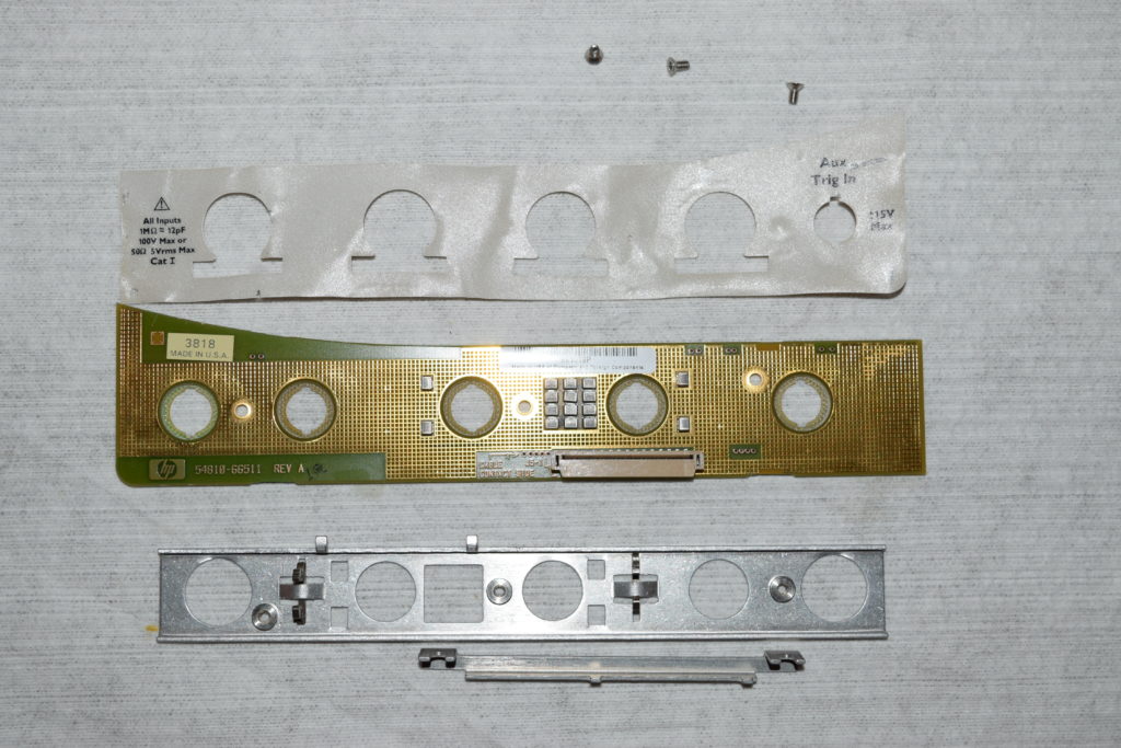
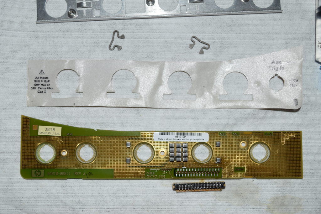
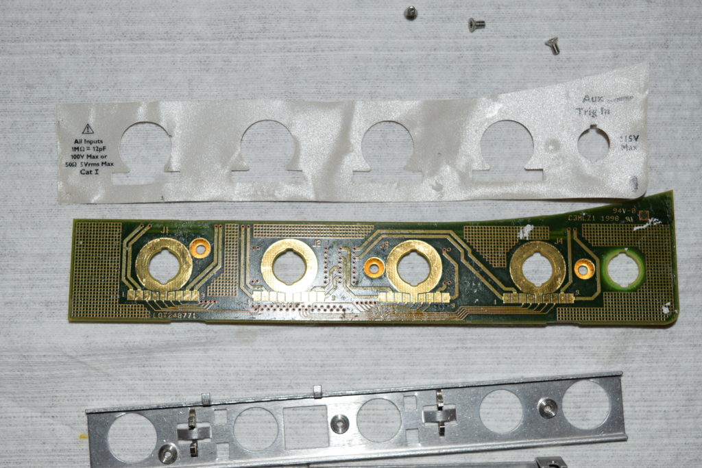
Teardown of Infiniium probe interface card 54810-66511

I have a bad probe interface card from a 4 channel unit. Since the label at the front is nearly impossible the transfer, and the screws was put on before the label covers it, plus the FFC connector is impossibly tight even for hot air to get there without much damage, it’s near impossible to save it with a 2 channel card.

Out of curiosity, I removed the label sheet to see what’s inside it:

The PCB is the same for 2 channels or 4 channels. The 2 channel version simply have channel 3 and the aux trigger hole covered (channel 4 is the external trigger port in a 2 channel model). So technically, you can cut out the excess label and cover up the “Ext Trig” text, but it won’t look professional. If it’s your personal unit, then feel free to go with the hack.

Loading

Infiniium front panel keypad 54810-66504 (2 channels vs 4 channels)

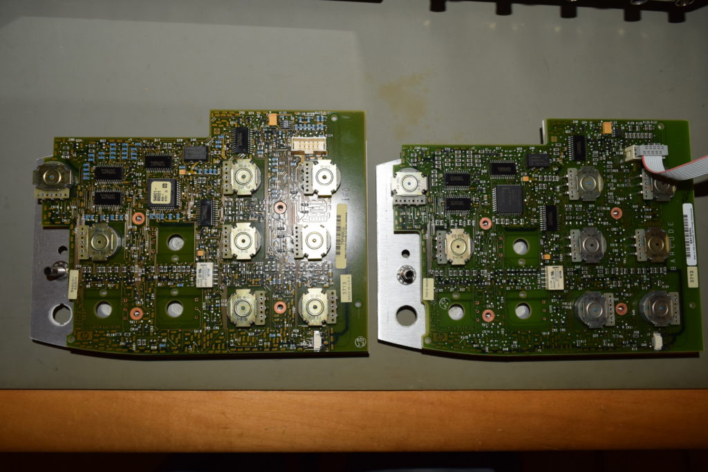
54810 series (first generation) Infiniium uses the same PCB for 2 channels and 4 channel models. They slap on a different rubber keypad sheet and the button labels depending on whether it’s a 2 channel or 4 channel model.

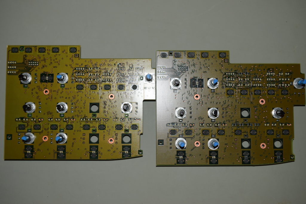
I received a 4-channel front panel keypad module that was ruined by ripped pads around the relay while trying to replace it. Instead of trying to fix it, I transferred the rotary encoders to a 2 channel PCB which are in abundance, and I noticed this:

It seems like HP/Agilent at some point tried to save a few pennies by skipping the SMD grains (resistors, capacitors, inductors, transistors, diodes) surrounding Channel 3 and 4 for the newer board on the right.

So if you are looking to repair a 4 channel front panel keypad with 2 channel PCB, you should preferentially select ones from the older lot which has all the parts for 4 channels populated except the rotary encoders. If not, time to get a pair of SMD hot tweezers and transfer the grains one by one.

Loading

Synthesized/Arbitrary Waveform/Function Generators: sampling rate matters

It’s basic (signal processing) mathematics that square waves (or any waveform with sharp edges) carry harmonics that doesn’t die fast enough, therefore not band-limited. The more sudden the transition is, the more harmonics you need to preserve to faithfully represent a signal in practice.

Unless the signal itself is known to be band-limited (like sine waves, classical modulation schemes, SRRC), it puts the burden on the test instruments involved to provide large bandwidths and the matching high sampling rate (needs to do better than Nyquist).

The technology today provides generous bandwidths and sampling rates for oscilloscopes at reasonable prices, but synthesized function/waveform generators with the same bandwidth/sampling rate can easily cost 10 times if not even more. For the money to buy a used not-too-old 500Mhz pulse generator, you can buy a 4GHz 20GS/s oscilloscope!

For oscilloscopes, users are often aware that the rounded square waves/transitions they see on the screen is due to bandwidth limitations, and will account for the reality distortion in their mind. If your square wave clocks are pushing the sampling rate of the scope and the combined bandwidth between the scope and the probes, you should very well expect that you cannot catch much glitches and pretty much use the oscilloscope as a frequency counter or check for modulations.

For synthesized signal generators, bandwidth and samplers are way more precious. Oscilloscopes generally has 8-bit vertical resolution (256 steps), but synthesizers typically has 12-bit vertical resolution (4096 steps) or better. There are imperfect techniques trading vertical resolution and sampling rate, but there is no free lunch. 

I have on my bench these 12-bit function generators:

  • an old Analogic 2045B (roughly US$1300, 400Mhz, 800MS/s, 2Mpts) and
  • a much more modern Agilent/HP 33120A (roughly US$600, 15Mhz, 40MS/s, 16Kpts)

that I’d like to illustrate the value of getting a higher bandwidth (and therefore higher sampling rate) unit. The 33120A has a much finer control over frequency/amplitude/offset steps (2045B only allows fixed point increments) and might have better noise characteristics and much smaller form factor considering Analogic 2045B is made in the 1970s and HP 33120A is made at least 20 years after that. I would have liked to keep only my 33120A or 33255B on my bench to save space, but once you’ve seen this screenshot, you’ll know why I’m still willing to cough up the space for 2045B:

The upper waveform (Channel 1, yellow) is a from Analogic 2045B while the lower waveform (Channel 2, green) is from HP 33120A. They are both set at around 15Mhz and you can see that when approaching the limit of the synthesizer, 33120A rounds off the square wave to almost a sinusoid.  Square waves gets ugly quickly above 10Mhz and this is as far as 33120A is capable of.

On the other hand, the square waves are bang-on for 2045B, and is still decent at around 50Mhz (my BNC cable starts to come in question). That’s why it’s still worth getting a high bandwidth synthesized function generator even if your budget only allows for clumsy old models if you use your function generator for something more than sinusoids.


Note that function generators are typically designed to pump out to 50Ω loads and the amplitude displayed in the function generator (V_{gen}) assumed so. That’s why beginners gets confused why they read 2V_{pp} when the function generators says 1V_{pp}: the function generator sends out nearly double the voltage so the potential divider formed between the 50Ω output impedance of the function generator and the 50Ω load impedance will split the voltage into half. If you set your oscilloscope to 1MΩ load, you are getting (2V_{gen})\frac{1MΩ}{1MΩ+50Ω}, which is nearly 2V_{gen}.

More importantly, if the load is not matched, the small capacitances in the chain will distort the waveform received by your oscilloscope severely at higher frequencies, so you can barely get a square wave at fundamental frequency above 2Mhz undistorted if you feed it into an oscilloscope with 1MΩ input impedance, while in reality the signal generator, cables, and oscilloscope can do much better.

Most cheap low bandwidth oscilloscopes (like 100Mhz) do not have 50Ω option. Nonetheless the impedance needs to be matched if you work with square waves at 2Mhz or above. Just buy a 50Ω feed-through BNC ‘termination’ adapter and plug it right at the 1MΩ input port. In reality, it’s a divider between 50Ω and (1MΩ//50Ω), with the scope seeing \frac{(1M//50)}{(1M//50)+50} of 2V_{gen}. For all practical purposes the oscilloscope sees (2V_{gen})\times0.5 or V_{gen}.

With 50Ω feed-through BNC ‘termination’ adapters, make sure you work out the impedance matching if you split the signals if it’s not the simple nearly 1:1 potential divider halving the voltage. At low frequencies, the amplitudes will be off, but when you start going into Mhz range and above, your signal will be distorted badly as well.


Loading


Loading