TDS 500~800 series Monochrome CRT Driver Repair

The most common mode of CRT display failure in the TDS 500~800 series (Monochrome models) is the flyback transformer. The symptom is that after leaving the screen on for a couple of hours, the screen started stretching vertically until it disappears.

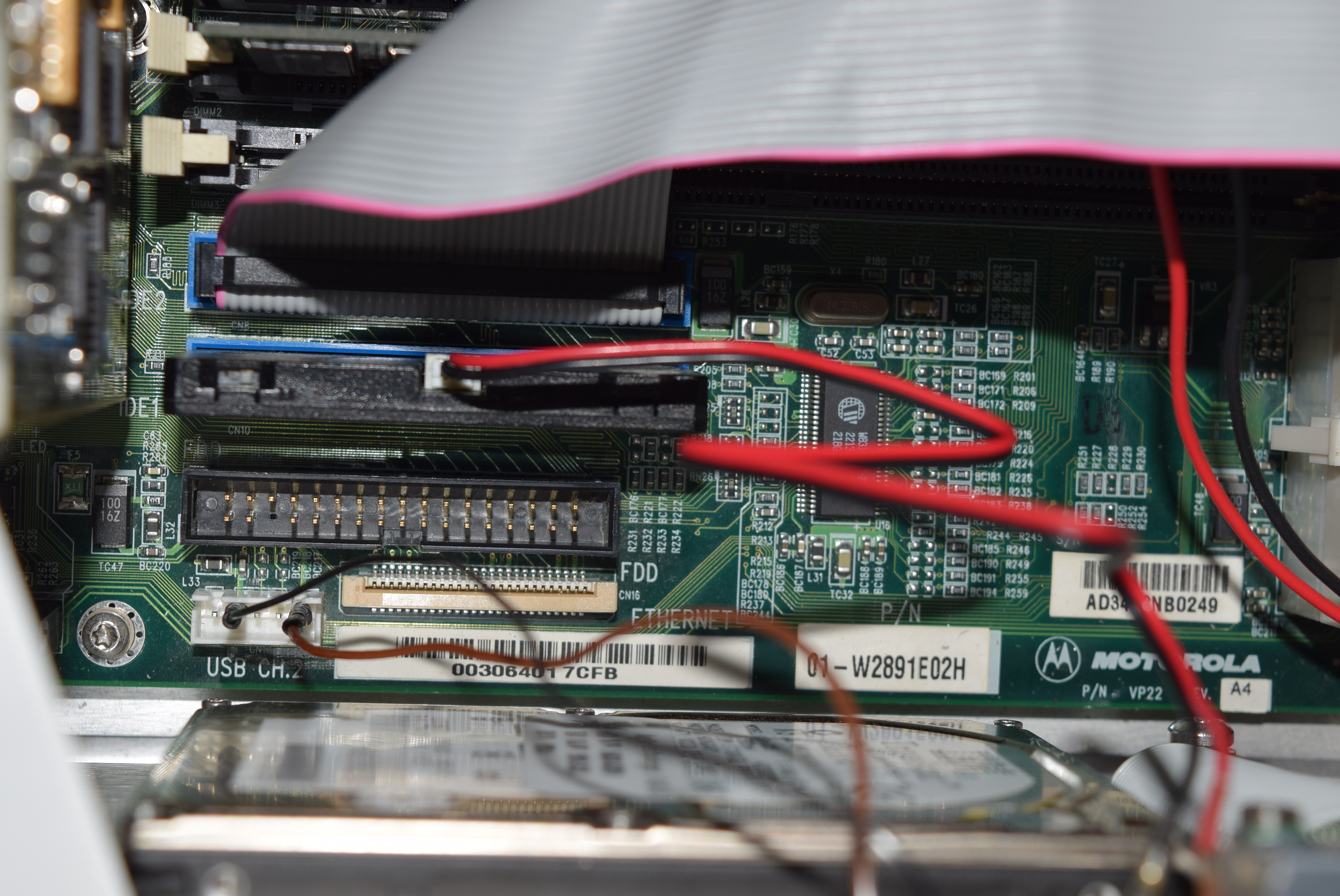
It also happens the failure only happens to a batch of CRT boards. The batch I’ve seen looks new (with modern markings that tells you the purpose of the trimpots) and lightly used, so I’m sure it’s infant mortality. Here’s the broken CRT driver board to be repaired:

There’s practically nowhere you can find this obsolete replacement because it’s not a common configuration. I sourced a batch from China that claimed the part number, and I spent whole day cursing the vendor when the flyback transformer arrived. Here’s what I saw:

The one on the right was the broken original flyback transformer, and two on the left were my new orders. Not only that the shapes are completely different, the number of pins doesn’t even match. WTF?!!!

The seller told me that it works. Forget about how to fit that in the board for a moment. How the f*** am I supposed to know which pins goes to which spot? Not to mention there are 11 dots when the original only has 8+1 (actually 7+1, pin#8 is not used). I said dots instead of pins because not all of them are populated with a pin, and the pins that are missing were not even consistent across the transformers in the batch.

I cannot even guess with a multimeter because it’s not a simple, uniform transformer. Even if I know which ones are connected, I could have ruined the whole thing by having the wrong number of coil turns/inductances because I switched a pair or two!

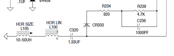
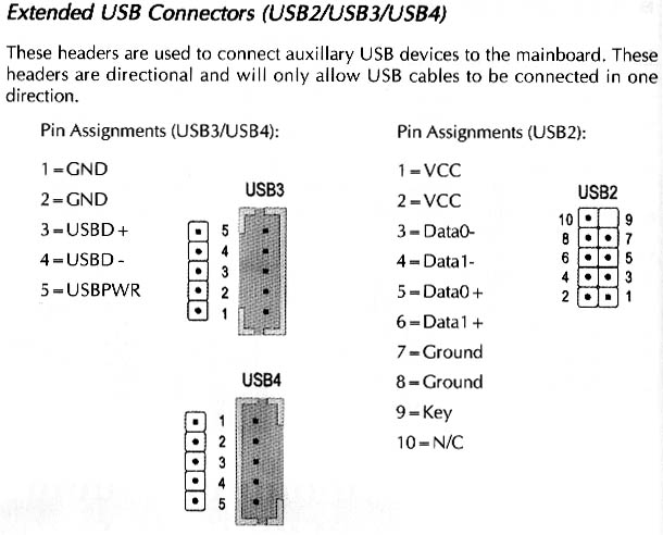
I had to push the seller really hard for him to dig up the actual mapping and draw me the pinouts on the pictures I’ve sent him (I’m sure the whole batch will be trash if I could not communicate with them in Chinese). The ‘product’ must have been designed and the manufacturing line ran by a bunch of village idiots. Nothing is right about it other than the windings inside are electrically usable (can’t even say compatible because I need to hack it really hard to get the correct display). Here’s the pinout:

Here’s another transformer that doesn’t have the ground pin (unnumbered), turns out the transformer works without it:

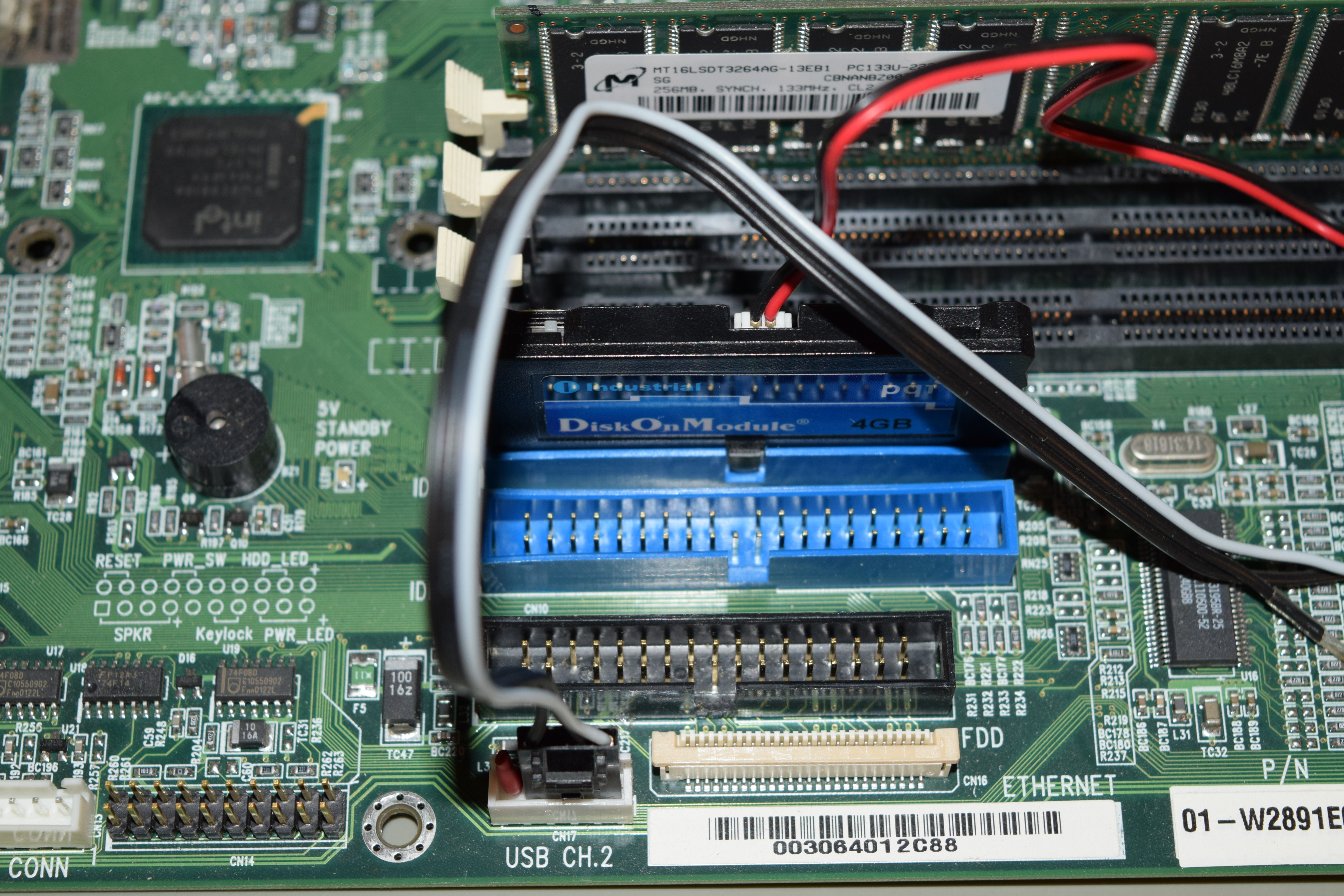
The space inside the oscilloscope case is pretty tight, and I managed to find one orientation that lines up with the case nicely, but it’s ugly as hell:

I held it down with hot-glue, caulk to stabilize it. A rubber band was put over it so that if the glue fails, the transformer won’t roll inside the compartment causing mayhem (later units I used cable ties since rubber band might deteriorate with heat. You get the idea.):

If you are not a hobbyist and don’t want the hassle of disassembling whole bunch of stuff just to take out the CRT driver, rebuild it with the said flyback transformer and re-tuning the CRT driver (not only it’s a huge pain, the working room is very tight if you don’t have the extension cables), I recommend sending the unit to me for a full CRT surgery (you pay for shipping costs both ways). I also charge a lot less if you combine it with other services such as re-capping (strengthening), NVRAM replacement, etc, in one trip.

Update (2023/07/02): the prices 6 years ago is no longer practical. Luckily nobody asked. This surgery is just way too much hassle to charge this little. If you have a big customer who really need to keep exactly the same model to avoid changing their process/certification/software, ask me for a spot quote. I usually give very generous combined discounts if there’s more than one thing to work on.

I don’t think anybody else have new compatible flyback transformers for these displays that has the same fate anymore. I’ll update this post when the ones I saved are used up.

Call me at 949-682-8145.

Loading

TDS 500 600 Series (and TDS 820) Monochrome CRT Horizontal Linearity

I have a batch of TDS 620A which everything looks shiny new, but the display will stretch vertically and eventually gone unstable after turning it on continuously for a long time.

Turns out there’s a specific batch of flyback transformer (120-1841-00) on the monochrome CRT driver board (640-0071-06) that has quite a bit of infant mortality. The newer the unit looks (of the CRT tube looks shiny new without burn-in), the more likely it’s a victim of the bad batch.

The transformer is almost impossible to source (other than getting another CRT driver board), but I was able to find a Chinese supplier who makes it. It was usable, but it’s a nightmare to get it on because it’s really done with the stereotypical Chinese (PRC) manufacturing caliber.  When I received the unit, it’s a WTF moment! Leave me a comment if you want me to write about it.

The replacement transformer is only pin and functionality compatible, but it’s not a drop in replacement (not even geometrically). The characteristics are different and I had to adjust the trimmers all over the place.

I was able to get the screen width I want by adjusting the variable inductor (L105, HOR SIZE) by nearly pulling ferrite rod out, but the horizontal linearity was way off (the left side is very squeezed):

I looked into the TDS520B Component Service Manual (Same CRT board circuit diagram) and found this:

But L100 looks like this, which doesn’t seems trimmable:

The right hand side is the same L100 choke I extracted from a CRT driver board (same model) that I’ve disposed of. I saw two suspicious pieces of metal-like objects strapped on the choke on the left (installed) which I haven’t seen in other identical boards. 

Thinking that by changing the magnetic property of the core, I can adjust the inductance of an otherwise non-adjustable inductor. I took a few bits of magnets sitting on my bench and swing it around the L100 choke, the horizontal display widens/narrows depending on which pole of the magnet is facing the L100 choke.

After a few trial and error, I picked the right amount of magnet discs to correct the horizontal linearity so the squares have roughly the same width:

I guess I cracked the code! Here’s the result of correction by magnet:


Loading

RTC / NVRAM in Test Equipment

HP Infiniium Series Atlas III Motherboard (Oldest generation Infinium oscilloscopes still branded as HP):

  • [RTC. There’s no exposed batteries] bq3287AMT = DS1288

Tektronix TDS Series (500, 600, 700, 800)

  • Older TDS (without alphabet suffix): Dallas DS1245Y
  • Model number that ends with ‘A’:  Dallas DS1650Y

The NVRAM in TDS series only contains the options data. Since I can reprogram the options, I can start with a blank NVRAM without reprogramming it). 

Will keep updating this page when I came across more test equipment.

Loading

Test instrument repair services (Specific models only)

There are a few used test instrument models that I’m familiar with the common problems. I moved onto the higher end, big ticket items so I wouldn’t bother acquiring them anymore.

Nonetheless, it hurts to see a piece of good equipment going to landfill. I’d be happy to repair the following models at a moderate rate (materials included, no fix no pay) below if anybody is interested:

  • HP 6515A power supply: $400 for a problematic unit, $300 when you send in a good one for preventative recapping (the capacitors are from 1970s! They are dying.).
  • HP/Agilent 54600 series oscilloscope: display got squeezed ($200), unit losing memory/time ($200), blown input channels due to excessive voltage ($300 for 1 channel + $100 per extra channel), unstable/cannot trigger ($500).
  • HP/Agilent (Older, non-Megazoom) Infiniium series: replacing OS hard drive ($250), cannot calibrate certain channels ($400 for 1 channel + $100 per extra channel).
  • HP/Agilent Infinium 5483X and above: refer to 54830 series post.
  • TDS 500, 600, 700 series oscilloscope: SPC fail without other symptoms ($500), Acq/Attenuator fail ($600), Proc board fail ($400), Color screen bubbled ($500), Cal initialization failed ($300), upgrading all possible software options ($200, free with any other service).

Contact me at 650-804-5024. All units must be delivered to Irvine, CA for service (and shipped back/picked up) at requester’s cost.

Loading

Tektronix S1001 DIP switch: Open pin 3 to boot for fast self-test (TDS 744, 744A, 684A, 784A)

Normally for most TDS 500 series oscilloscopes, the DIP switch (S1001) typically all closed for normal operation. The only described use in the service manual is opening pin 6 and 7 to reveal the hidden composite test pattern screen for display adjustment.

However, I got a TDS 744 scope that boots very slow. Almost 5 mintues! To the extent that it’s unbearable. Initially I thought it’s just the non-A type booting slow. Nonetheless, I got a chance to open up another TDS 744A with boots much faster (in half a minute) with calibration seals on, and I noticed the pin 3 of S1001 is opened. Initially I thought it was out of place so I closed it again. Guess what? A slow 5 minute boot sequence!

I suspected opening pin 3 of S1001 puts the oscilloscope in the quick boot mode. I experimented with the pin 3 opened and manually initiating the full blown self-test (utility menu). Turns out I was correct! The full self-test is 5 minutes!

Since it was the settings from the calibration house, I looked up the TDS 744A/684A/784A service manual and noticed that the factory default is with pin 3 opened, while the old TDS 544A manual says pin 3 is closed. I suspect that the self-test for the new models 744/744A/684A/784A is unbearably long that the Tek decided to have it disabled for boot-up self-test.

In any case, try opening pin 3 to have the scopes boot faster!


Loading