This is based on the Raspberry Pi implementation of the Toner chip reset:
https://gist.github.com/joeljacobs/c57550cdb4e68e3b86d6b89fb58f305d
I am using a Raspberry Pi Zero W so the chip is BCM2835 instead and I can use 100Kbps/400KBps instead of 9600 baud as in the original code
The electrical pins we need is clustered on to top left, Pins 1 (3.3V), 3 (I2C SDATA), 5 (I2C SCLK), 9 (Ground)

While looking for the pinouts (https://pinout.xyz/pinout/i2c), I discovered a useful tool called i2cdetect that allows me to find out the address of the chips which means I can write a program automatically figure out the right image to load to the chip without looking:
sudo apt-get install i2c-tools
sudo i2cdetect -y 1

Please remind me in the comments section if you find out who should I credit it to.
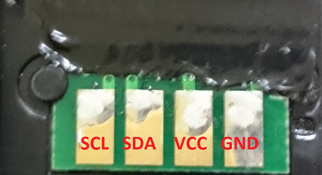
Since I don’t have cheap pogo pins lying around, I took the 2.4mm pitch (the standard size used in PC, Arduino and Raspberry Pi) jumper block I have (so all pins are set at equal lengths to make simultaneous contact) and hope somehow there’s 4 pins that kind of align with the contact, and it did. See pictures here:

You might be worried about shorting into the next pin or hooking something up in reverse damaging the chips, but luckily the chips survived. My guess is that it’s a good design to put the Vcc next to Ground on one side instead of making it symmetric so the polarity can be reversed. When reversed, SCL is set to low (Ground), SDA is pulled up to Vcc while there is no power supply, so no damage is done. Brilliant! The worst case for my poorly aligned jumper block is that SDA and Vcc might touch each other, but it doesn’t matter because it’s a perfectly legal hookup (just not communicating)!
So no worries if you didn’t touch the pins right! The only case it might go wrong is if you intentionally flip the block and slide it by two pins (reversing Vcc and Ground). Other cases (you are likely going to run into) are pretty much data lines getting hooked high or low levels while power lines not getting any supplies.
I’ve designed the program that it’ll detect the chip if you hook it up right and immediately program the chip (takes only a second), so you don’t have to hold the jumper for too long to worry about unstable contacts.
#!/bin/bash

# This program detects rewrite the toner chips to "full" for a Ricoh SP C250SF/DN Printer using Raspberry PI (defaults to BCM2835 models such as Raspberry PI Zero)

# The chip data is in file named "black" "cyan" "magenta" and "yellow".
# The pad closest to the edge is GND (-> Pin 9), followed by VCC (-> Pin 1) , DATA (-> Pin 3), and Clock (-> Pin 5).

# Be sure i2c is enabled and installed (it's turned off by default) on Raspbian

# This line is disabled because it takes too long to unregister i2c_bcm2835 to start from a clean slate
# modprobe -r i2c_bcm2835

# This program needs sudo permissions as it involves direct access to hardware
if [[ $EUID -ne 0 ]]; then
  echo "Need root permissions as this code involves direct hardware access. Try sudo"
  exit 2
fi

# Sets the baud rate
modprobe i2c_bcm2835 baudrate=400000

# Install i2cdetect if not exist (This idiom uses short-circuit OR for conditional exec)
command -v i2cdetect > /dev/null 2>&1 || {sudo apt-get install i2c-tools}

# Create I2C address to color map
COLORS=( [50]="yellow" [51]="magenta" [52]="cyan" [53]="black" )
# Detect chip I2C address
I2C_address=$( sudo i2cdetect -y 1 | grep 50 | sed -e 's/50: //;s/-- //g' )
# Keep the 0x5* address lines since only 0x50~0x53 is valid. Strip the 50: header, discard all "--" entries, and you are left with the detected address
HEX_I2C_address="0x$I2C_address"

# LED flash function(s)
target_device="/sys/class/leds/led0/brightness"
# This accounts for breaking changes (by renaming led0 to ACT) from Bookworm
[ -f ${target_device} ] || target_device="/sys/class/leds/ACT/brightness"

function turn_off {
  echo 0 > ${target_device}
}
function turn_on {
  echo 1 > ${target_device}
}
function toggle {
  # PI Zero only has 1 power LED which is on/off
  # Reads 0 for OFF and 255 for ON
  readin=$(cat ${target_device})
  # Condition 255 to 1 to reduce platform dependency
  state=$[$readin>0]
  # Not equal to 1 is XOR (flip)
  flip=$[$state != 1]
  # Display output
  echo $flip > ${target_device}
}

function flash_once {
  period=${1:-0.5}

  toggle
  sleep $period

  toggle
  sleep $period
}

function flash {
  times=${1:-1}
  period=$2
  for((i=1; i<=times; i++)); do
    flash_once $period
  done
}

echo "Detecting toner chip ..."
turn_off
if [ -v COLORS[I2C_address] ]; then
  # Meat
  color=${COLORS[I2C_address]}
  echo "Detected toner chip for color: $color"

   # "address" counter sync up with the hex code index in file
   printf "Writing"
   address=0;
   datafile="${BASH_SOURCE%/*}/${color}"
   for i in $(cat $datafile); do
     i2cset -y 1 ${HEX_I2C_address} $address $i; || break
     address=$(($address +1));
     printf .
     flash 1 0
   done
   echo "Done!"
   turn_on
else
  echo "Invalid I2C address for SP C250DN/SF toner chips. ${I2C_address}"
  turn_on
  exit 4
fi
Turns out Linux’s dot sourcing (bash calling) syntax is relative to your current folder, not the scripts’ folder. So if you have one script calling another in the same folder when you are not currently at the same folder as the script (e.g. startup automation), the relative paths will be wrong. So instead of ./ , you should use this prefix instead:
${BASH_SOURCE%/*}/I chose to flash the board’s only LED light quickly before starting and blink slowly a few times after it’s done for visual clues. It’s entirely optional. Here’s the guts of the code without the fancy indicators:
#!/bin/bash

# Sets the baud rate
modprobe i2c_bcm2835 baudrate=400000

# Create I2C address to color map
# Note that the dictionary/hash keys below are abusively pretending the hex are decimals
# since the i2cdetect()'s output is text showing hex values without the "0x" prefix
# I got away with this because the only 4 possible choices are 0x50 .. 0x53
# so I never ran into 'A...F'. Do not imitate this. The output of i2cdetect()
# is already messy to parse so it'd make the code complicated to keep track of hex.
COLORS=( [50]="yellow" [51]="magenta" [52]="cyan" [53]="black" )

# Detect chip I2C address
I2C_address=$( sudo i2cdetect -y 1 | grep 50 | sed -e 's/50: //;s/-- //g' )
HEX_I2C_address="0x$I2C_address"

if [ -v COLORS[I2C_address] ]; then
  # Meat
  color=${COLORS[I2C_address]}

  # "address" counter sync up with the hex code index in file
  address=0;
  for i in $(cat ${color}); do
    i2cset -y 1 ${HEX_I2C_address} $address $i || break
    address=$(($address +1));
  done
else
  echo "Invalid I2C address for SP C250DN/SF toner chips: ${I2C_address}"
fi
Download the package. Run program_toner
This downloadable is old and might not reflect the update directly improvements directly reflected on the blog page’s code listing. I’ll get to it when I have some time.
Just in case if people are wondering. The L01 chip’s datasheet is here:
To make a dedicated Raspberry Pi Zero device to run this script (program_toner) repeatedly on boot, I made a script loop_program_toner that runs the same program as infinite loop.
Since writing starts immediately once the chip is identified (no reason to hold the pogo pins for longer than needed), once the chip is detected, whether the writing finished successfully or not, threre’d be 5 seconds of delay so you can reseat the pogo pins (on write failure) or remove the pogo pins (so it won’t unnecessarily rewrite the chip again).
#!/bin/bash

if [[ $EUID -ne 0 ]]; then
  echo "Needs root permissions. Try sudo"
  exit -2
fi

while :
do
  bash "${BASH_SOURCE%/*}/program_toner"
  if (($?)); then
    # Wait longer to give time to detatch probe once chip is detected
    # whether the process completed successfully or not
    sleep 5;
  else
    sleep 1;
  fi
done
There are a few steps needs to auto make this automated:
- Have a user account dedicate to autorun the program on boot. In the example here, we’ll use Raspberry Pi’s default
adminaccount - Auto-logged on by running
sudo raspi-config, select (1) System Option > (S5) Boot / Auto Login > (B2) Console Autologin - Bless the said account with password free sudo rights: Run
sudo visudoand add this to the end (replaceadminwith something else if you chose a different username)
admin ALL=(ALL) NOPASSWD:ALL- Call
loop_program_tonerin./profileor ~/.bashrc (startup script). Can place this at the bottom if your package folder is~/spc250dn:
sudo ./spc250dn/loop_program_tonerThe path can start with . or ~ because you are starting with at home folder anyway.
EDIT (2023-11-1): Linux people lack the backward compatibility decency again! They changed /led0 and /led1 to /ACT and /PWR under /sys/class/leds and they don’t have the decency to put in a symbolic link so old code won’t break! WTF!
Do they have an idea how many code they’ll break and how many man hours they will waste the world to discover this breaking change when updating the distro? Non-caught exceptions just fall through and shows up as mysterious error messages!
If you want people to get the memo and change their code to match a more sensible notation, feel free to put in a warning stub, but hell no to just flip a switch and watch the world scream! This is apparently not a difficult decision to make when adding backward compatibility would be a huge project because of some catch-22 conditions!
ARM: dts: Standardise on the upstream LED names · raspberrypi/linux@ea14f14 (github.com)
Raspberry Pi Zero only has one LED which is /led0 (/ACT), so ignore /led1 (/PWR).
![]()


