One day I was working on an old first generation Agilent Infiniium oscilloscope (namely 54810A) while I was too tired and rushed, I accidentally short-circuited the main acquisition board because I forgot to reconnect the probe-compensation port pin back to the acquisition board after taking out the front-panel and putting it back: the jumper with exposed metal (the heat-shrink over it was a little short the way Agilent manufactured them) swiped over something and I heard a loud bang, the scope shuts off, and I smelled the magic smoke.
My heart sank. Just saving a few extra minutes being careful checking everything (despite I opened and closed those front panel ten dozen times) I thought I lost an expensive PCB that’s almost the cost of the whole oscilloscope, and even if I can fix it, it might drain me at least a week.
Given that I know a short fried something (there’s a bad smell). I didn’t even bother to turn the unit on again until I’ve located what has fried. Turning something that you know it’s fried on again just risks further damage as it can load other parts of circuits.
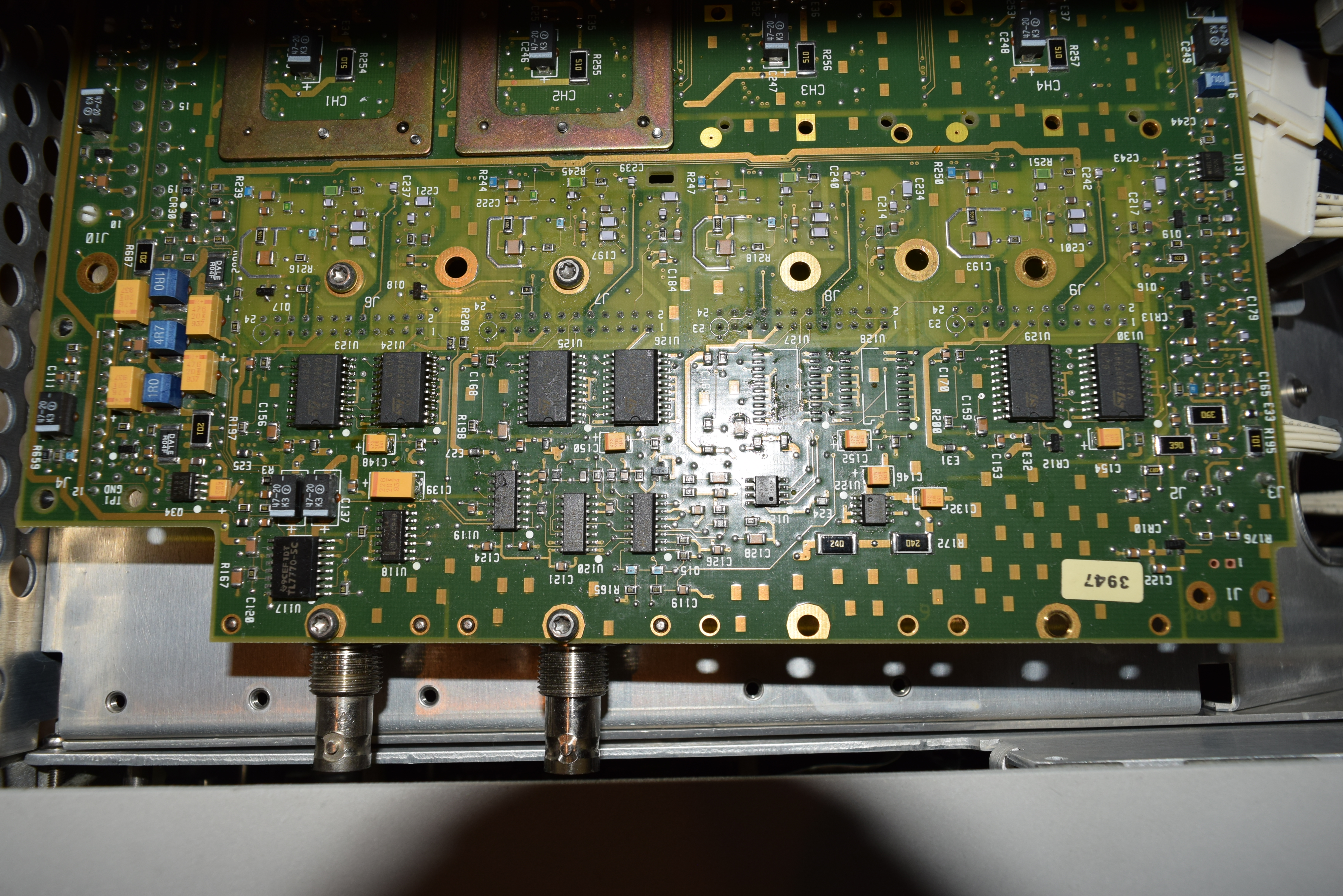
Following the smell, I found a burnt IC on the other side of the board (needs to be painfully disassembled as the front panel /w BNC nuts needs to be taken out all over again), and I looked up the part number: ST L6201. It’s sitting on Channel 1’s front end section between the attenuator relay block and the ADC hybrid and there are 2 of them per channel.
Given the location of the component, it’s clearly the L6201 populated at Ch3’s slot is not used since it’s a 2 channel oscilloscope. So I transferred the chips to replace the broken ones at Ch1:
What is an H-bridge driver (L6201), that’s supposed to control motors, doing in an oscilloscope, especially the front-end section? I googled “H-bridge driver in oscilloscope” and nothing relevant turned up. Then I went back and read a little more on how an H-bridge driver is really used. L6201 is a DMOS Full Bridge Driver with four power MOSFETs (switches) that basically sends current through an inductive load (typically motor) that might have stored energy (momentum) that might need to be drained (brake) to stop faster.
Turns out it’s a slick way to drive mechanical relays in the input attenuator given the amount of due care needed to accurately manage the current demand and switch transitions. There are 3 relays in the attenuator module. I suspect up to two relays can be switched with each L6201 by placing a diode in serial with with a relay coil, and repeat it (in parallel) with the diode reversed in the other branch. Is it an overkill? Let me know in the comments section. Please see the comments section
I also noticed, while dealing with the main acquisition board for 54615B/54616B, there is a L293D chip under the attenuator block shield for each channel. It’s a 4 channel driver with half-bridge, also intended to drive inductive loads. This one is more explicit about being used to drive relay solenoids as well as motors. So this is nothing new; It’s just not too many people talked about using it on oscilloscope architectures.
![]()
There is a total of 4 bridges in those 2 chips. the relay coils are connected in a star configuration, 1 bridge drives the mid point and the rest 3 the ends. This way they can invert the polarity on any of the coils. Also, if they need to switch 2 relays (going from 200 mv/div to 500 mv/div) you can hear 2 clicks. The reason is that they can not switch 2 relays at the same time.Report
Thanks a lot for the valuable insights!Report